 |
|||
|
|
|||
|
|
|||
| ||||||||||
|
|
 t o hold the clutch springs compressed and remove
(8) Install a second bolt that secures the outer
the bolts.
drum to flange. Tighten this bolt securely.
(7) Relieve the pressure on the puller and
( 9 ) Complete the installation in reverse order
r e m o v e the puller and the steering clutch pressure
o f removal. Torque the bolts (1, fig. 6-82) and (4)
plate (1, fig. 6-86).
t o the value given in table 1-2.
( 8 ) Remove the clutch disc assemblies (1, fig.
(10) Refer to paragraph 6-14 and adjust the
6-85) and the clutch driving discs (4) from the
brakes.
i n n e r drum (5), numbering the disc assemblies and
c. Disassembly.
discs as they are removed.
NOTE
Position the steering clutch assembly on blocks,
NOTE
allowing at least .5 inches of clearance.
If the same driving discs are reused, they must be replaced on
the inner drum with the same face up, but better wear
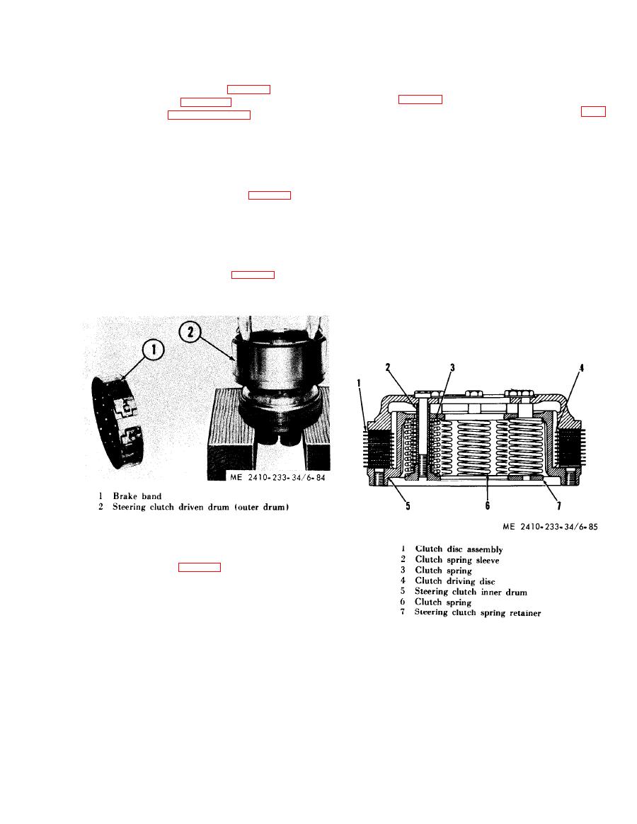
(1) Remove the brake band (1, fig. 6-84) from
distribution can be obtained if they are switched from the top
the outer drum (2)
to the bottom of the clutch stack.
( 2 ) Remove the outer drum from the steering
clutch assembly.
(9) Remove the clutch springs (3) and (6) and
the clutch spring sleeves (2).
NOTE
(10) The steering clutch spring retainer (7),
The overall thickness of ten new disc assemblies and
o v e r which the springs and sleeves are placed, can
nine new driving discs is given in table 1-4. If the
now be removed.
overall thickness is less than the minimum overall
width, they should be replaced.
NOTE
Before assembly, check the discs for warping and
check, also, the disc assemblies for excessive wear and
roughness. Inspect for broken springs and excessive
wear on retainer.
(3) Place the plate on the bolt, insert the bolt
t h r o u g h the center of the steeering clutch assembly
and place the plate (2, fig. 6-86) over the bolt.
(4) Place a hydraulic puller over the bolt so
t h a t the base is against the plate. Extend the ram
a b o u t 11 / 2 i n c h e s .
( 5 ) Install a heavy washer and a nut onto the
bolt and tighten it until it is against the puller.
( 6 ) Apply just enough pressure with the puller
|
|
Privacy Statement - Press Release - Copyright Information. - Contact Us |
