 |
|||
|
|
|||
|
Page Title:
Section Il. STEERING CLUTCHES, BRAKES AND BEVEL GEAR |
|
||
| ||||||||||
|
|
 Section Il. STEERING CLUTCHES, BRAKES AND BEVEL GEAR
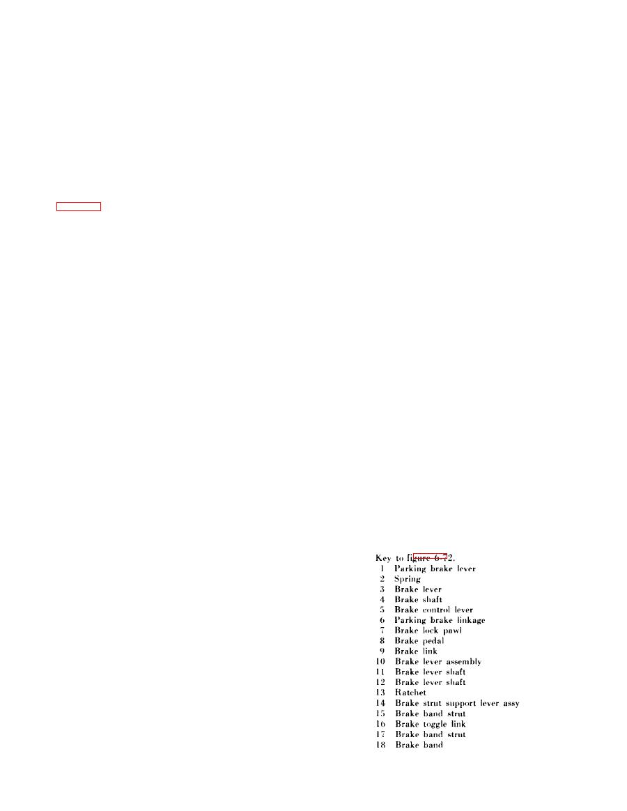
b r a k e lever assembly (14) to rotate about the brake
6-13. General
l e v e r shafts (11 and 12). The struts (15) and (17)
This section contains information on the brakes,
a r e forced against the lugs on the brake band (18),
s t e e r i n g clutches, steering clutch hydraulic controls,
c a u s i n g the band to contract on the steering clutch
and bevel gear.
o u t e r drum. When the brake pedal is released, the
6-14. Brakes
spring ( 2 ) r e t u r n s t h e b r a k e p e d a l , l i n k a g e a n d
a . General. T w o c o n t r a c t i n g - b a n d - t y p e b r a k e s ,
b r a k e hand to the unapplied position. The parking
which operate independently of one another, are
brake is engaged by depressing either or both brake
used to supplement the action of the steering clutch
pedals and pushing the parking brake lever (1)
or to stop the tractor. E i t h e r or both brakes can be
d o w n . This moves the parking brake linkage (6)
held in the locked position by the brake lock pawls
forward, engaging the pawl (7) with the ratchet
( 7 , fig. 6-72). These pawls are actuated by a single
(13). The brakes are held in the applied position by
hand lever. The operation of both brakes is the
the pawls that hold the brake linkage in the
same. When the brake pedal (8) is depressed, the
engaged position.
b r a k e control linkage moves the brake control lever
CAUTION
(5) forward. The brake shaft (4) and brake lever
The brake pedals should be depressed
( 3 ) rotate and pull up on the brake link (9). This
b e f o r e the lever (1) is pulled upward to
f l a t t e n s the brake toggle links (16) and causes the
release the brakes. This will prevent
brake strut support lever assembly (10) and the
d a m a g e to the ratchet teeth or the pawl.
|
|
Privacy Statement - Press Release - Copyright Information. - Contact Us |