 |
|||
|
|
|||
|
Page Title:
WINCH CONTROL LEVERS AND LINKAGE REPLACEMENT |
|
||
| ||||||||||
|
|
 TM 5-2410-233-23
WINCH CONTROL LEVERS AND LINKAGE REPLACEMENT
THIS WORK PACKAGE COVERS
Removal, Installation
INITIAL SETUP
References
Applicable Configuration
Tractor with winch
Tools and Special Tools
Tool kit, general mechanic's (Item 112, WP 0185
Equipment Condition
Materials/Parts
Machine parked on level ground (TM 5-2410-233-
Grease, GAA (Item 15, 0184 00)
10)
Tag, marker (Item 35, WP 0184 00)
Engine OFF and cool (TM 5-2410-233-10)
Lockwasher (4 and 20)
Winch cool (TM 5-2410-233-10)
Pin, cotter (10)
REMOVAL
NOTE
If tractor is equipped with a winterized cab, remove sound suppression panels.
1.
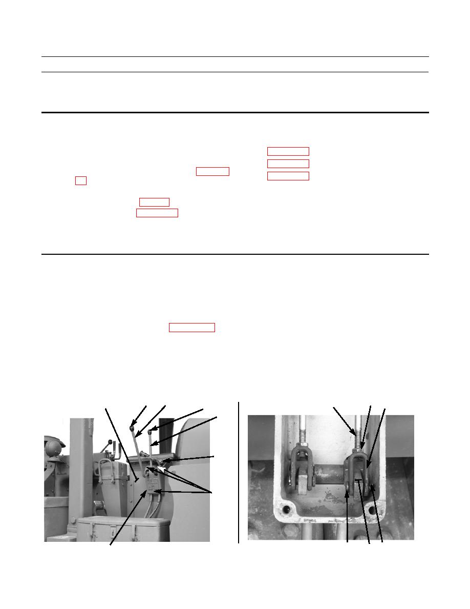
Remove two knobs (1) from winch control levers (2).
2.
Remove left armrest from seat base (WP 0137 00).
3.
Remove three capscrews (3) and lockwashers (4) that secure control bracket (5) to seat base (6). Discard lockwashers.
4.
Remove control bracket (5) from seat base (6). Remove control lock (7).
5.
Completely back off nut (8) on control cable (9).
6.
Remove cotter pin (10), pin (11) and clevis (12) from winch control lever (2). Discard cotter pin.
7.
Remove control cable (9) from clevis (12).
8.
Repeat steps 5 through 7 for other control cable (9).
8
2
1
9
6
12
1
2
7
3,4
(HIDDEN)
386-088
10
386-087
11
2
5
|
|
Privacy Statement - Press Release - Copyright Information. - Contact Us |