 |
|||
|
|
|||
|
Page Title:
SEAT, SEAT BELT AND SEAT BASE ASSEMBLY REPLACEMENT |
|
||
| ||||||||||
|
|
 TM 5-2410-233-23
SEAT, SEAT BELT AND SEAT BASE ASSEMBLY REPLACEMENT
THIS WORK PACKAGE COVERS
Removal, Installation
INITIAL SETUP
References - Continued
Tools and Special Tools
Tool kit, general mechanic's (Item 112, WP 0185
Shop equipment, common no. 1 (Item 94, WP 0185
Sling, nylon (Item 100, WP 0185 00)
Lifting equipment, 200 lb capacity
Personnel Required
Materials/Parts
Two
Lockwasher (7, 13 and 17)
References
Equiptment Condition
Machine parked on level ground (TM 5-2410-233-
10)
REMOVAL
1.
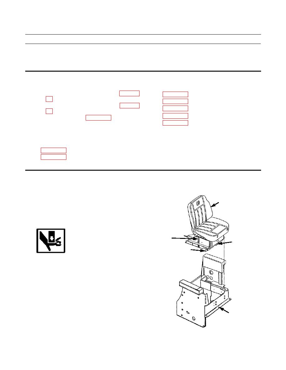
Pull rod assembly (1) at front of seat vertical adjuster
3
(2) forward to release seat lock.
2.
Tilt seat (3) forward then slide seat back and straight
up so hinge pins (4) slide out of seat base assembly
(5).
2
1
WARNING
4
Use extreme caution when handling heavy
parts. Provide adequate support and use assis-
tance during procedure. Failure to follow this
warning may cause injury.
NOTE
Seat with vertical adjuster weighs 46 lb (21 kg).
3.
Remove seat (3) with vertical adjuster (2) from tractor.
5
386-468
|
|
Privacy Statement - Press Release - Copyright Information. - Contact Us |