 |
|||
|
|
|||
|
|
|||
| ||||||||||
|
|
 TM 5-2410-233-23
WINCH CONTROL LEVERS AND LINKAGE REPLACEMENT - CONTINUED
0142 00
REMOVAL- CONTINUED
9.
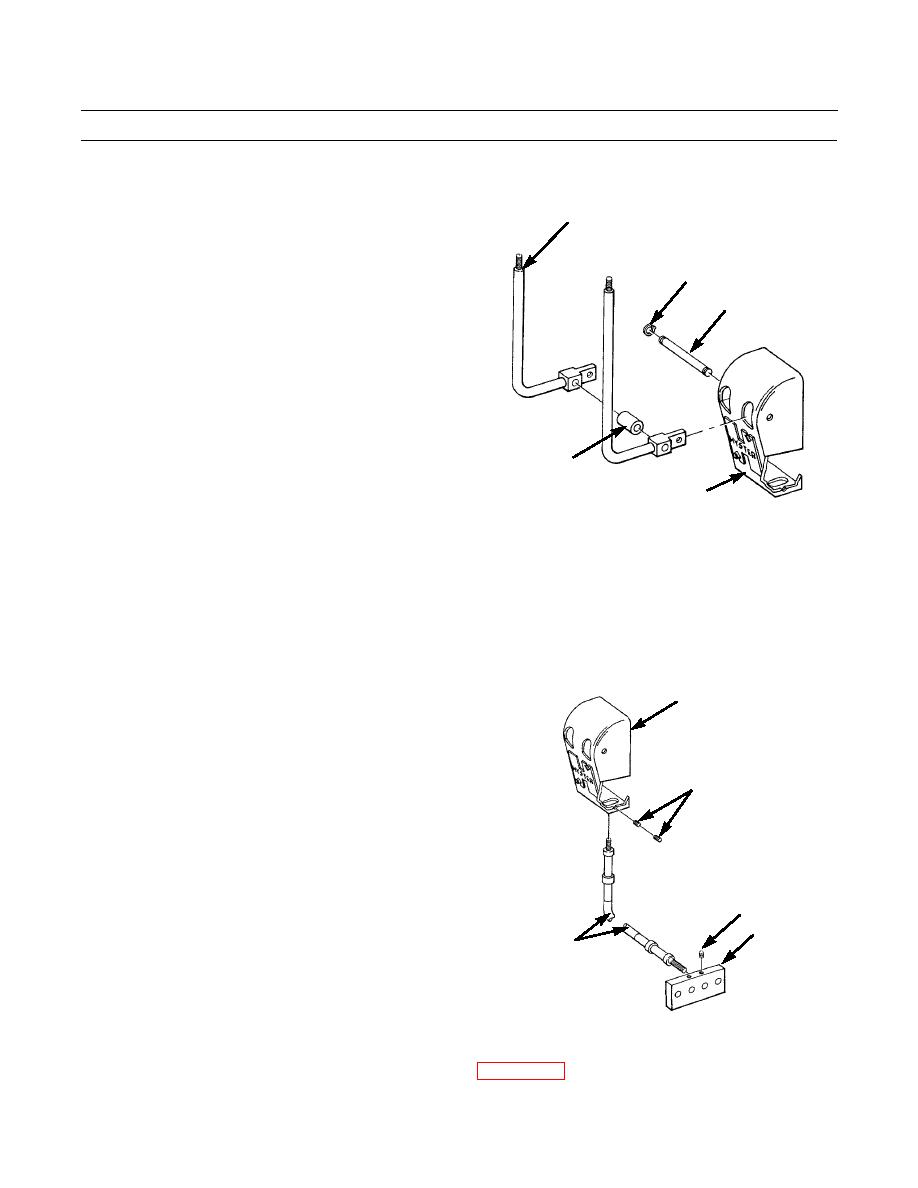
Remove snap ring (13), pin (14) and spacer (15) secur-
2
ing control levers (2) to control bracket (5).
13
14
15
5
386-089
NOTE
Tag control cables to ensure correct installation.
10.
Remove setscrew (16) to release control cable (9) from control bracket (5). Repeat step for other cable.
11.
Remove two setscrews (17) from cable block (18).
5
12.
Remove two capscrews (19) and lockwashers (20)
from cable block (18). Discard lockwashers.
16
17
18
9
386-095
13.
Remove top access cover from winch control valve housing (WP 0140 00).
0142 00-2
|
|
Privacy Statement - Press Release - Copyright Information. - Contact Us |