 |
|||
|
|
|||
|
Page Title:
WINCH CONTROL LEVERS AND LINKAGE ADJUSTMENT |
|
||
| ||||||||||
|
|
 TM 5-2410-233-23
WINCH CONTROL LEVERS AND LINKAGE ADJUSTMENT
THIS WORK PACKAGE COVERS
Adjustment
INITIAL SETUP
References
Applicable Configuration
TM 5-2410-233-10
Tractor with winch
Equipment Condition
Tools and Special Tools
Winch control valve access cover removed (WP
Tool kit, general mechanic's (Item 112, WP 0185
Winch control levers and control bracket removed
from seat base (WP 0142 00)
ADJUSTMENT
1.
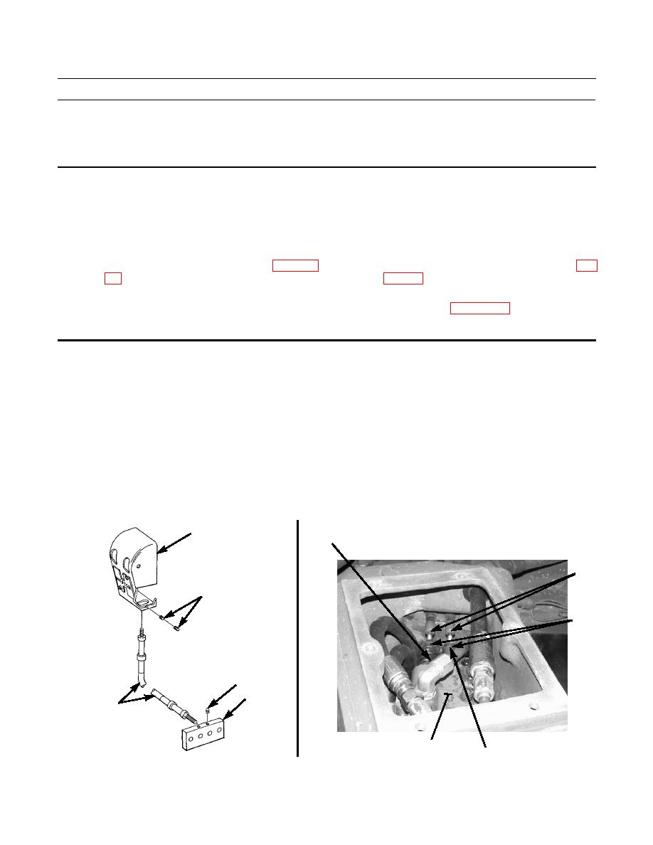
Loosen two setscrews (1) and release control cables (2) from control block (3).
2.
Loosen two setscrews (4) and release control cables (2) from control bracket (5).
NOTE
Control valve (A) is the winch brake valve and control valve (B) is the winch cable valve.
3.
Completely loosen two nuts (6) from brake and winch cable rod ends (7) at winch control valve (8).
5
A
7
4
6
1
3
2
386-092
8
B
386-095
|
|
Privacy Statement - Press Release - Copyright Information. - Contact Us |