 |
|||
|
|
|||
|
Page Title:
TRANSMISSION SELECTOR LEVER AND LINKAGE MAINTENANCE |
|
||
| ||||||||||
|
|
 TM 5-2410-233-23
TRANSMISSION SELECTOR LEVER AND LINKAGE MAINTENANCE
THIS WORK PACKAGE COVERS
Removal, Installation, Adjustment
INITIAL SETUP
Equipment Condition
Tools and Special Tools
Battery disconnect switch in OFF position (TM 5-
Tool kit, general mechanic's (Item 112, WP 0185
2410-233-10)
Floor plates removed (WP 0135 00)
Materials/Parts
Seat with vertical adjuster removed (WP 0137 00)
Lockwasher (4, 8, 22, 27 and 36)
Transmission selector lever, guard and guide cover
removed (WP 0084 00)
Nut, self-locking (32)
WARNING
Ensure battery disconnect switch is in OFF position before performing maintenance on transmission selec-
tor lever and linkage. Failure to follow this warning could result in injury or damage to equipment.
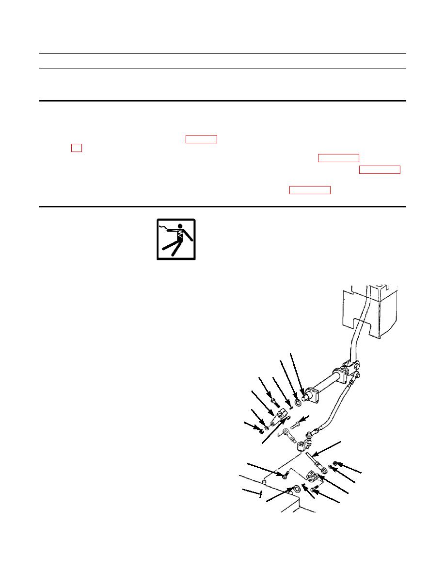
REMOVAL
1.
Disconnect one end of rod assembly (1) from lever (2)
by removing nut (3), lockwasher (4) and capscrew (5).
Discard lockwasher.
2.
Disconnect other end of rod assembly (1) from lever
(6) by removing nut (7), lockwasher (8) and capscrew
(9). Discard lockwasher. Remove rod assembly.
18
17
3.
Loosen capscrew (10) and remove lever (2), key (11)
and washer (12) from transmission (13).
15 16
4.
Remove nut (14) and capscrew (15) from lever (6) and
6
slide lever, key (16) and spacer (17) from shaft (18).
8
9
7
1
14
10
3
4
13
2
11
12
5
386-406
|
|
Privacy Statement - Press Release - Copyright Information. - Contact Us |
