 |
|||
|
|
|||
|
Page Title:
DRIVE SPROCKET SHAFT REPLACEMENT |
|
||
| ||||||||||
|
|
 TM 5-2410-233-23
DRIVE SPROCKET SHAFT REPLACEMENT
THIS WORK PACKAGE COVERS
Removal, Installation
INITIAL SETUP
Tools and Special Tools - Continued
Tools and Special Tools
Puller, hydraulic (Item 76, WP 0185 00)
Tool kit, general mechanic's (Item 112, WP 0185
Puller, hydraulic (Item 77, WP 0185 00)
Puller, mechanical (Item 80, WP 0185 00)
Shop equipment, general purpose repair (Item 97,
Pump, hydraulic ram (Item 84, WP 0185 00)
Adapter (Item 2, WP 0185 00)
Sling, nylon (Item 100, WP 0185 00)
Spacer, sleeve (Item 103, WP 0185 00)
Adapter, coupling (Item 5, WP 0185 00)
Wrench, spanner (Item 120, WP 0185 00)
Adapter, pin (Item 6, WP 0185 00)
Lifting equipment, 400 lb capacity
Clip, retaining (Item 16, WP 0185 00)
References
Forcing screw, mechanical puller (Item 24, WP
TM 5-2410-233-10
Personnel Required
Head, socket install (Item 31, WP 0185 00)
Two
Link, pin (Item 45, WP 0185 00)
Equipment Condition
Nut, plain, round (Item 50, WP 0185 00)
Track roller frame removed (WP 110 00)
Pin (Item 55, WP 0185 00)
Track drive sprockets/hubs removed (WP 0118 00)
Pin, lock (Item 56, WP 0185 00)
removed (WP 0100 00)
Pin, straight, headless (Item 59, WP 0185 00)
REMOVAL
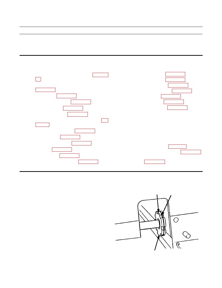
1.
Remove lockring (1) and pin (2) from nut (3) at steer-
2
1
ing clutch case.
CAUTION
DO NOT remove nut from threaded portion of
sprocket shaft. Failure to follow this caution
could result in thread damage on shaft and in
steering clutch case.
2.
Loosen nut (3) on steering clutch case until there is a
1/8 in. (3.2 mm) gap between nut and steering clutch
case.
386-441
3
|
|
Privacy Statement - Press Release - Copyright Information. - Contact Us |