 |
|||
|
|
|||
|
|
|||
| ||||||||||
|
|
 TM 5-2410-233-23
TRANSMISSION CONTROL VALVES REPLACEMENT - CONTINUED
0094 00
INSTALLATION - CONTINUED
7.
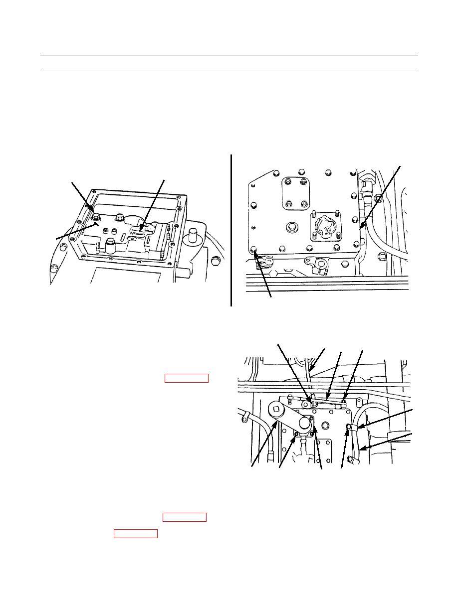
Position pressure control valve (24) on top of selector valve (27). Secure with three washers (23) and capscrews (22).
Tighten capscrews to 35 lb-ft (47 Nm).
8.
Install new gasket (21) and cover (20) to transmission with 14 new lockwashers (19) and capscrews (18).
20,21
24
22,23
27
386-389
386-388
18,19
9.
Install nut (17) and rod (16). Install capscrew (15),
13,14,15,17
16 12
9,10,11
new lockwasher (14) and nut (13).
10.
Install rod (12) onto transmission with capscrew (11),
new lockwasher (10) and nut (9).
11.
Adjust rods (12 and 16) as required (WP 0083 00).
12.
Install new gasket (8) and spout (5) on transmission
with four new lockwashers (7) and nuts (6).
3
13.
Remove plug from end of hose assembly (4). Connect
hose assembly to spout (5).
4
14.
Secure hose assembly (4) to transmission with two
clips (3), new lockwashers (2) and capscrews (1).
386-387
1,2
5
6,7
8
15.
Check and adjust relief valve setting IAW Relief Valve Setting Adjustment below.
16.
Install seat and seat base assembly (WP 0137 00).
17.
Install floor plates (WP 0135 00).
0094 00-4
|
|
Privacy Statement - Press Release - Copyright Information. - Contact Us |