 |
|||
|
|
|||
|
Page Title:
RELIEF VALVE SETTING ADJUSTMENT |
|
||
| ||||||||||
|
|
 TM 5-2410-233-23
TRANSMISSION CONTROL VALVES REPLACEMENT - CONTINUED
0094 00
RELIEF VALVE SETTING ADJUSTMENT
1.
Perform direction clutch test (primary setting) (WP 0098 00).
CAUTION
Wipe valve body clean prior to disassembly. Perform disassembly in a clean work environment. Contami-
nation of transmission could result in premature failure.
NOTE
Disassembly of pressure control valve is authorized to add or remove spacers in order to
adjust relief valve setting.
Each 0.062 in. spacer will change setting by 15 psi (103 kPa).
Each 0.036 in. spacer will change setting by 8.5 psi (59 kPa).
Each 0.010 in. spacer will change setting by 2.5 psi (17 kPa).
Lightly coat all components with clean oil before installation.
2.
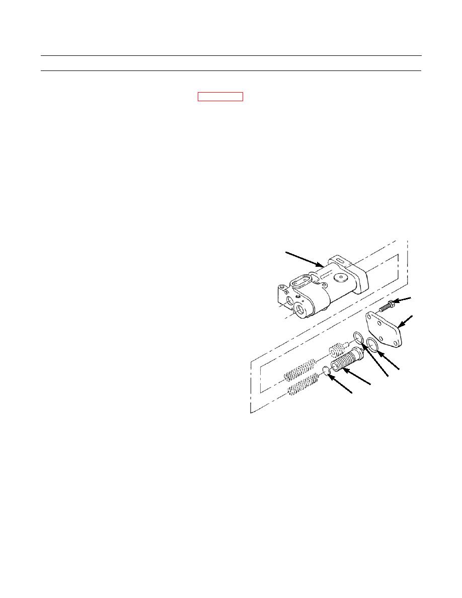
Add or remove spacers (41) to valve body (35) of pressure control valve to adjust relief valve setting:
a.
Remove bolts (36) and cover (37) from valve
35
body (35).
b.
Remove two O-rings (38 and 39) and discard.
c.
Remove piston (40). Add or remove spacers (41)
to achieve correct relief valve setting.
36
d.
Install piston (40) and two new O-rings (38 and
39).
37
e.
Install cover (37) to valve body (35) with bolts
(36). Tighten bolts to 35 lb-ft (47 Nm).
38
39
40
41
386-393
3.
Operate machine and check transmission for proper operation (TM 5-2410-233-10).
END OF WORK PACKAGE
0094 00-5
|
|
Privacy Statement - Press Release - Copyright Information. - Contact Us |
