 |
|||
|
|
|||
|
Page Title:
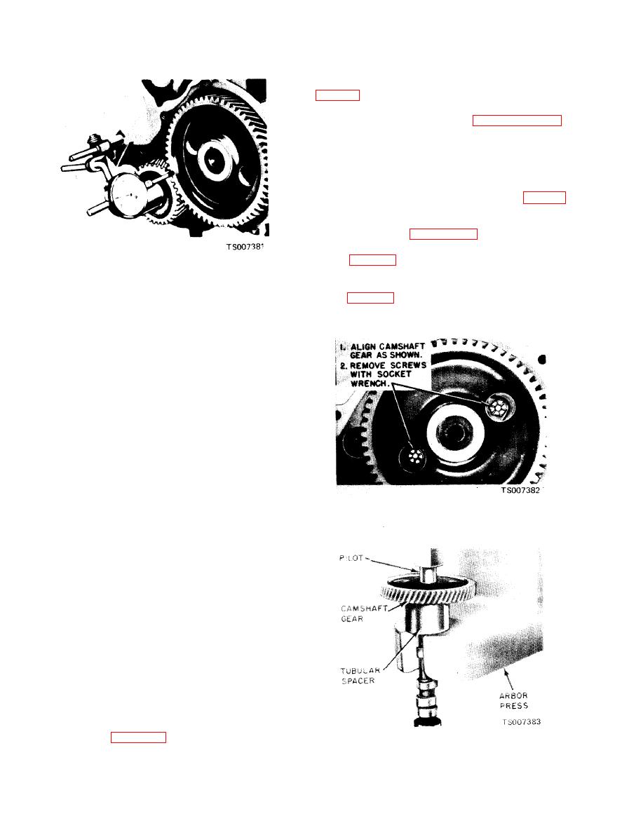
Figure 6-52. Checking Timing Gear Runout. |
|
||
| ||||||||||
|
|
 TM 10-3930-633-34
(6) Remove the capscrew and washer from
the end of the crankshaft. Remove the damper
(7) Remove the oil pan and related parts by ,
following the procedure under paragraph 6-43.
Remove the oil pump screen and inlet tube
assembly.
(8) Remove the cylinder front cover and
discard the gasket.
(9) Check the camshaft end play, the timing
gear backlash and the timing gear runout (para 6-
38).
(10) Turn the crankshaft to align the timing
marks as shown in figure 6-36.
(11) Remove the camshaft thrust plate
screws (fig. 6-53). Remove the camshaft. Avoid
damaging the camshaft lobes during removal.
Press the camshaft out of the gear in an arbor
press (fig. 6-54). Remove the key, thrust plate
(2) Hold the camshaft gear against the
and spacer.
thrust plate, and zero the indicator.
( 3 ) Rotate the crankshaft to turn the
camshaft, while holding the camshaft gear
against the thrust plate.
(4) Check gear runout through one complete
revolution of the camshaft.
(5) If the gear runout exceeds specifications,
remove it and check for burrs or foreign particles
on or between the camshaft and gear joining
flanges. Check the runout. If it still exceeds
specifications, replace both gears.
(6) Follow the above procedure to check
crankshaft gear runout.
a. Removal.
(1) Disconnect the spark plug wires at the
spark plugs and disconnect the secondary high
tension wire at the ignition coil. Remove the
distributor cap and spark plug wires as an
assembly.
(2) Disconnect the fuel outlet lines at the fuel
pump. Remove the fuel pump mounting bolts and
position the fuel pump out of the way.
( 3 ) Disconnect the vacuum line at the
distributor and the primary wire at the coil.
Remove the distributor.
(4) Remove the valve rocker arm cover.
Loosen the rocker arm stud nuts, move the rocker
arms to one side and remove the pushrods in
sequence. Place the pushrods in a rack so they can
be installed in their original locations.
(5) Remove the valve pushrod cover; then
remove the valve lifters in sequence, using the
tool shown in figure 6-6. Place the valve lifters in
a tray or rack to facilitate installation in the same
sequence in which they were removed.
|
|
Privacy Statement - Press Release - Copyright Information. - Contact Us |
