 |
|||
|
|
|||
|
Page Title:
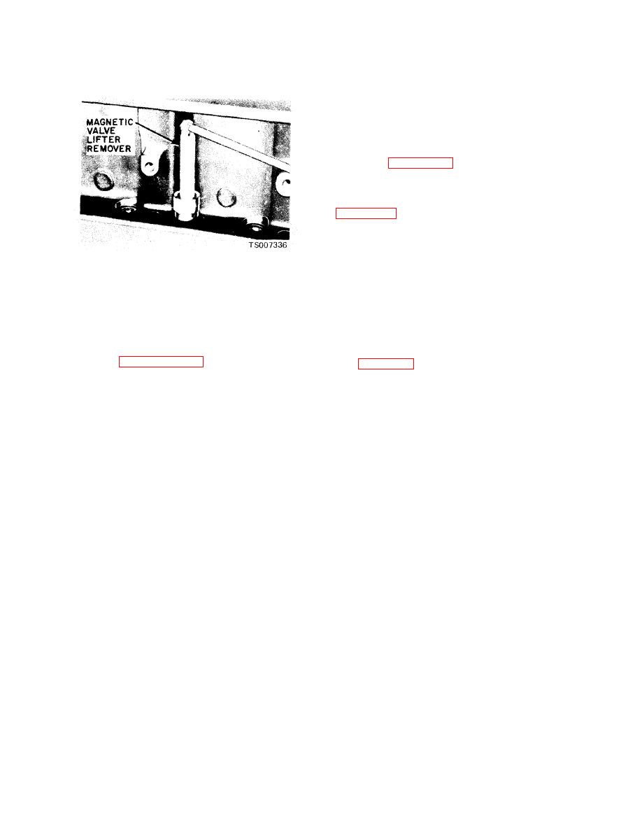
Figure 6-6. Value Lifter Removal. |
|
||
| ||||||||||
|
|
 TM 10-3930-633-34
(15) Remove the flywheel and engine rear
cover plate.
(16) Remove the oil pan and oil pump and
pickup tube assembly. Discard the gaskets and
seals.
(17) Check the camshaft end play, the
timing gear backlash and the timing gear runout
(Section VIII). Position the camshaft gear as
shown in figure 6-53 and remove the camshaft
thrust plate screws. Remove the camshaft, thrust
plate and gear as an assembly.
(18) Remove the crankshaft gear as shown in
(19) Remove any ridge and/or deposits from
the upper end of the cylinder bores. Remove the
cylinder ridge with a ridge cutter. Follow the
instructions furnished by the tool manufacturer.
Never cut into the ring travel area in excess of
(12) Remove the water pump (TM 10-3930-
1/32 inch when removing ridges.
633-12).
(20) Make sure all bearing caps (main and
(13) Remove the carburetor, intake and
connecting rod) are marked so that they can be
e x h a u s t manifold and cylinder head as an
installed in their original locations. Turn the
assembly (TM 10-3930-633-12).
c r a n k s h a f t until the connecting r o d being
(14) Remove the crankshaft damper as
removed is down. Remove the connecting rod cap.
outlined in paragraph 6-36. Remove the cylinder
See figure 6-7.
front cover. Remove the crankshaft front oil seal
from the cylinder front cover.
|
|
Privacy Statement - Press Release - Copyright Information. - Contact Us |
