 |
|||
|
|
|||
|
|
|||
| ||||||||||
|
|
 TM 9-2320-312-24-2
Specifications Section
Guideline For Reusable Parts And Salvage
(7) Diameter of cylinder bore .. 110.025 0.025 mm
Operations, SEBF8192, "Specifications and Salvage
(4.3317 0.0010 inch)
for Cylinder Blocks on 3114, 3116, 3126 and 3126B
Engines"
(8) Distance from the centerline of the crankshaft
bore to the top surface of the cylinder
Guideline For Reusable Parts And Salvage
block .. 322.00 0.17 mm (12.677 0.007 inch)
Operations, SEBF8261, "Installing a 7C-6208
Cylinder Sleeve in 3114 and 3116 Engines and a
(9) Front camshaft bearing joint location
107-7604 Cylinder Sleeve in 3126 Engines"
(10) Bore diameter in the cylinder block for the front
camshaft bearing ............... 70.000 0.025 mm
i01839706
(2.7559 .0010 inch)
Crankshaft
(11) Front camshaft bearing oil hole
SMCS Code: 1202
Note: The front camshaft bearing is installed with
the bearing oil hole (11) in alignment with the oil
hole in the cylinder block and the bearing joint (9)
in the position that is shown.
(12) Tighten the bolt to the following
torque. ...................... 70 10 Nm (50 7 lb ft)
(13) Bearing cap
Width of the main bearing
cap ................................... 159.995 0.020 mm
(6.2990 .0008 inch)
Width of the cylinder block for the main
bearing ............................. 160.000 0.018 mm
(6.2992 .0007 inch)
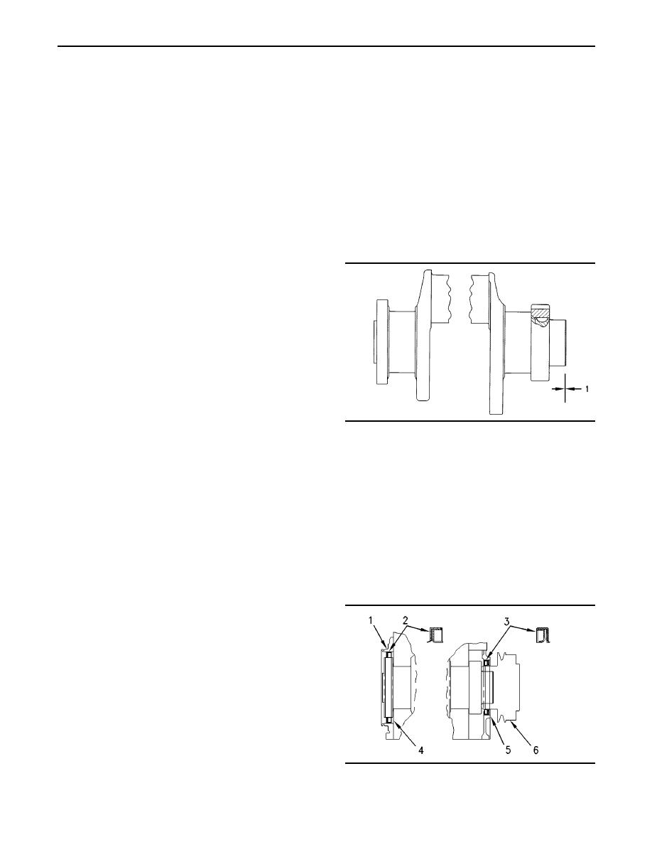
g00939552
Illustration 35
(14) Distance from the centerline of the crankshaft
(1) Crankshaft end play ................. 0.07 to 0.32 mm
bore to the pan rail ..... 110.00 mm (4.331 inch)
(0.003 to 0.013 inch)
(15) Location of the sequence number for the
bearing cap
i01733982
Crankshaft Seals
(16) Main bearing cap bolts
SMCS Code: 1160; 1161
Install the bearing caps with the sequence number
to the right. The order is 1 through 7 (front to rear).
Note: For the complete procedure on removing and
installing the crankshaft seals, refer to Disassembly
1. Apply 4C-5593 Anti-Seize Compound to the bolt
and Assembly.
threads (16) and face of the washers.
2. Tighten bolts (16) on each bearing cap.
Tighten to the following torque. ......... 54 7 Nm
(40 5 lb ft)
3. Tighten bolts (16) on each bearing cap again.
Tighten the bolts by another one quarter of a
turn. ............................................ 90 5 degrees
(17) Bore in the cylinder block for the seven main
bearings ............................. 95.000 0.013 mm
(3.7402 0.0005 inch)
g00291469
Illustration 36
Note: Additional information on reconditioning
procedures can be ordered. Refer to the following
documents:
|
|
Privacy Statement - Press Release - Copyright Information. - Contact Us |