 |
|||
|
|
|||
|
Page Title:
DIAGNOSTIC CONNECTOR REPLACEMENT |
|
||
| ||||||||||
|
|
 TM 9-2320-312-24-1
DIAGNOSTIC CONNECTOR REPLACEMENT
THIS WORK PACKAGE COVERS
Removal, Installation
INITIAL SETUP
Materials/Parts-Continued
Maintenance Level
Tag, marker (Item 58, WP 0165 00)
Unit
Washer, lock (P/N 361-88) (4)
RPSTL Reference
References
Group 170, Figure 7
Electrical Schematics--Foldouts
Tools and Special Tools
Tool kit, general mechanic's (Item 35, WP 0166 00)
Materials/Parts
Equipment Condition
Strap, tiedown (Item 57, WP 0165 00)
Battery disconnect switch in OFF position
REMOVAL
1.
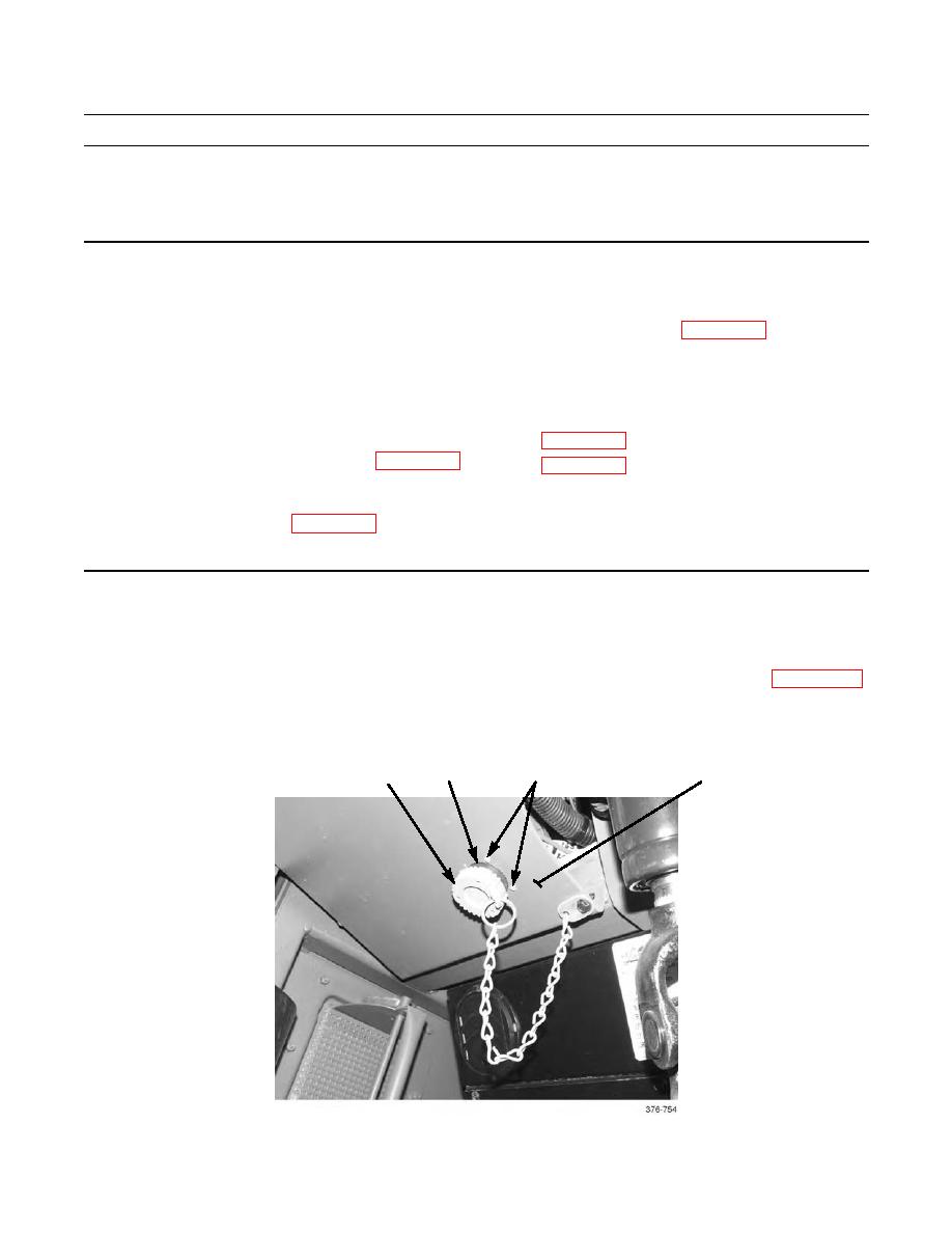
Remove cap (1) from diagnostic connector (2).
2.
Remove upper-front and lower-left instrument panel plates, to gain access to diagnostic connector wiring (WP 0100 00).
3.
Remove four nuts (3), lockwashers (4), and screws (5) and pull diagnostic connector (2) free from panel (6). Discard
3,4,5
2
1
6
|
|
Privacy Statement - Press Release - Copyright Information. - Contact Us |