 |
|||
|
|
|||
|
Page Title:
BLADE AND PUSHARM ASSEMBLY REPLACEMENT |
|
||
| ||||||||||
|
|
 TM 5-2410-237-23
BLADE AND PUSHARM ASSEMBLY REPLACEMENT
THIS WORK PACKAGE COVERS
Removal, Installation
INITIAL SETUP
References
Tools and Special Tools
Tool kit, general mechanic's (Item 122, WP 0250
Shop equipment, common no. 2 (Item 104, WP
Lifting equipment, 1,000 lb capacity
Personnel Required
Three
Materials/Parts
Oil, lubricating (Item 23, 24 or 25, WP 0249 00)
Equipment Condition
Rag, wiping (Item 29, WP 0249 00)
Machine parked on level ground (TM 5-2410-237-
Tag, marker (Item 37, WP 0249 00)
10)
Lockwasher (32)
Implements fully lowered to ground (TM 5-2410-
237-10)
Wood cribbing, 4 in. x 4 in. x 12 in. long
Wire, 1/16 in. dia x 24 in. long
Hydraulic system pressure relieved (WP 0241 00)
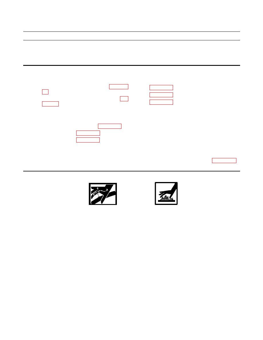
WARNING
Do NOT remove hydraulic tank filler cap or disconnect or remove any hydraulic system line or fitting
unless hydraulic system pressure has been relieved. Hydraulic system pressure can be over 2500 psi (17,238
kPa), even with engine and pump OFF. To relieve pressure, lower all hydraulic attachments to the ground
and shut down engine. Move control levers through all operating positions, then SLOWLY loosen hydraulic
tank filler cap. After maintenance, tighten all connections before applying pressure. Escaping hydraulic
fluid under pressure can penetrate the skin, causing serious injury or death.
|
|
Privacy Statement - Press Release - Copyright Information. - Contact Us |