 |
|||
|
|
|||
|
|
|||
| ||||||||||
|
|
 TM 5-2410-237-23
BLADE AND PUSHARM ASSEMBLY REPLACEMENT - CONTINUED
0235 00
REMOVAL
1.
Place wood cribbing under pusharms of tractor.
3
2.
Remove four capscrews (1), washers (2) and upper
1,2
radiator grille (3).
4,5
3.
Remove four capscrews (4), washers (5) and lower
radiator grille (6).
4.
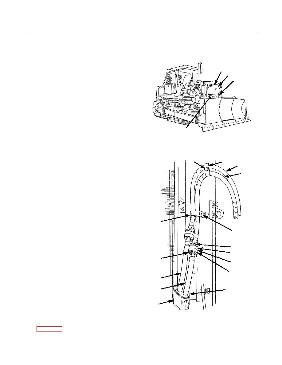
Remove capscrew (7) and clamp (8) from tilt cylinder
hoses (9 and 10) and radiator guard.
5.
Remove capscrew (11) and clamp (12) from tilt cylin-
der hoses (9 and 10) and radiator guard.
6.
Remove two capscrews (13), washers (14), nuts (15)
6
and clamp (16) from radiator guard. Open clamp and
387-774
separate hoses (17 and 18).
CAUTION
7
8
9
Before disconnecting hydraulic lines and
10
fittings, clean area to prevent contamina-
tion and premature failure of the hydrau-
lic system.
NOTE
Tag hydraulic hoses to ensure correct
installation.
Use a suitable container to catch any
oil that may drain from system. Dis-
12
pose of oil IAW local policy and ordi-
nances. Ensure all spills are cleaned
11
up.
7.
Remove four capscrews (19), eight washers (20), split
24,20
flanges (21 and 22), plate (23) and four nuts (24). Sep-
arate hoses (10 and 18).
21
19,20
8.
To separate hoses (9 and 17) repeat step 7.
23
NOTE
22
17
Forming a loop will close the system and
prevent dirt and moisture contamination.
18
13,14,15
9.
Connect hose (9) to hose (10) with split flanges (21
and 22) and plate (23). Install eight washers (20), four
capscrews (19) and nuts (24).
16
10.
Connect hoses (17 and 18) by following procedure in
387-775
step 9.
11.
Disconnect both lift cylinders (25) from blade (26)
0235 00-2
|
|
Privacy Statement - Press Release - Copyright Information. - Contact Us |