 |
|||
|
|
|||
|
Page Title:
AIR FILTER INDICATOR REPLACEMENT |
|
||
| ||||||||||
|
|
 TM 5-2410-237-23
AIR FILTER INDICATOR REPLACEMENT
THIS WORK PACKAGE COVERS
Removal, Installation
INITIAL SETUP
Equipment Condition
Tools and Special Tools
Tool kit, general mechanic's (Item 122, WP 0250
Engine OFF and cool
References
Materials/Parts
TM 5-2410-237-10
Nut, self-locking (8)
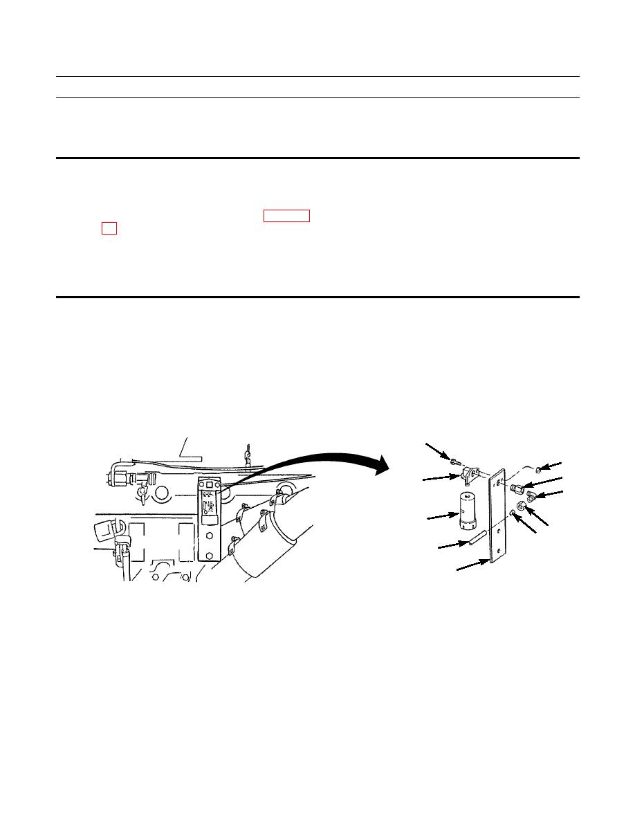
REMOVAL
1.
Remove nut (1) from elbow (2).
2.
Separate tubing (3) from elbow (2). Take care not to lose insert (4).
3.
Remove fitting (5) and elbow (2).
4.
Remove air filter indicator (6) from adapter (7).
5.
Remove two self-locking nuts (8), bolts (9) and adapter (7) from bracket (10). Discard self-locking nuts.
9
8
5
7
2
6
1
4
3
10
387-384
INSTALLATION
1.
Install adapter (7) to bracket (10) with two bolts (9) and new self-locking nuts (8).
2.
Install air filter indicator (6) into adapter (7).
3.
Install fitting (5) and elbow (2).
4.
Connect tubing (3) to elbow (2). Make sure insert (4) is placed in tubing (3).
5.
Install nut (1) on elbow (2).
6.
Check air filter indicator for proper operation (TM 5-2410-237-10).
END OF WORK PACKAGE
|
|
Privacy Statement - Press Release - Copyright Information. - Contact Us |
