 |
|||
|
|
|||
|
|
|||
| ||||||||||
|
|
 TM 5-2410-237-23
DRIVE SPROCKET SHAFT REPLACEMENT - CONTINUED
0142 00
INSTALLATION - CONTINUED
8.
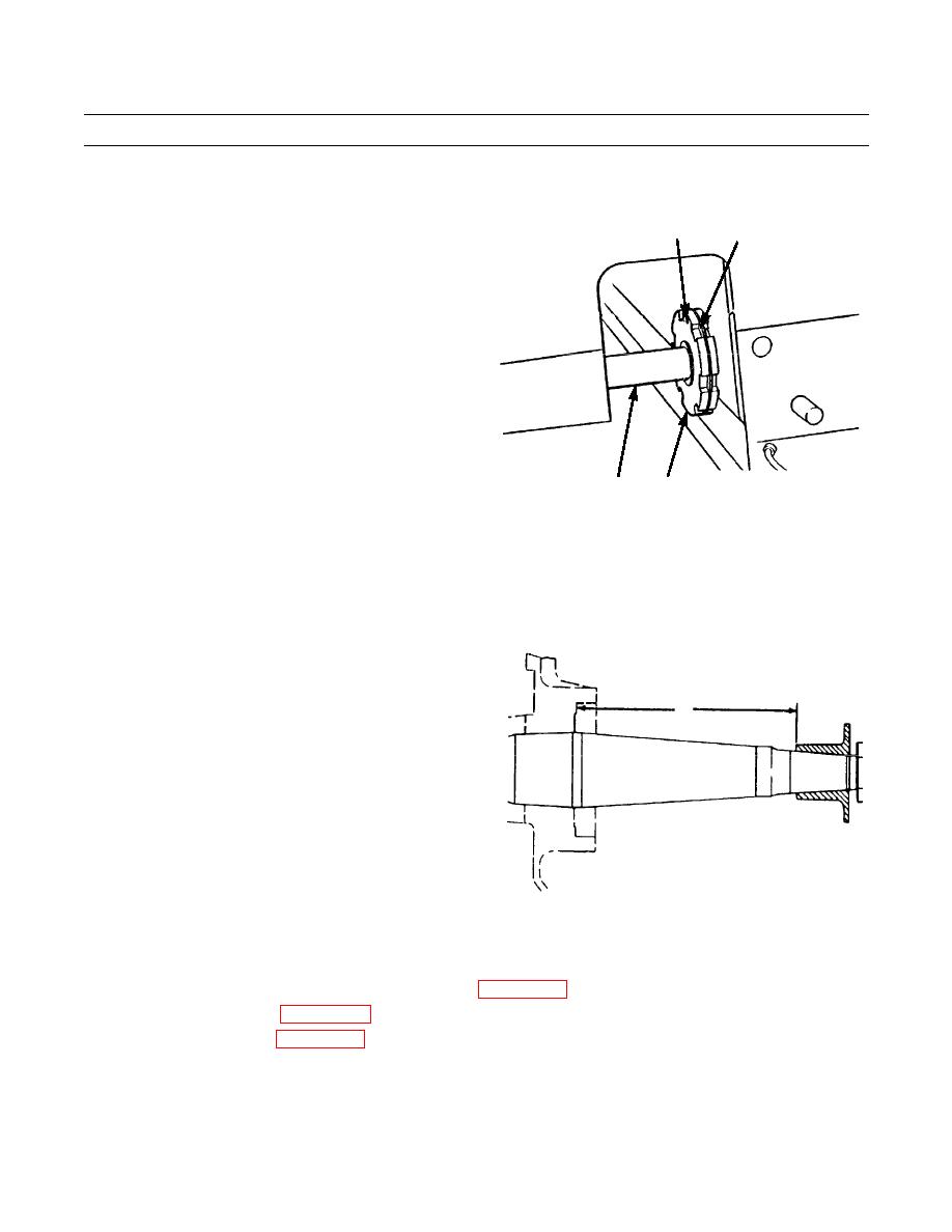
Install nut (3) on end of sprocket shaft (5). Tighten nut
to 750 lb-ft (1020 Nm).
2
1
9.
Release pressure on hydraulic cylinder (15).
387-610
3
5
WARNING
Ensure pressure is off cylinder before attempting to remove hydraulic pump. Failure to follow this warning
could result in personal injury and damage to equipment.
10.
Remove tooling from sprocket shaft (5) and gear case (8).
11.
Measure distance (B) from inner edge of holder
assembly to bottom of counterbore for inner bearing
cup in gear case (8). Distance should be 17.258 +/-
B
0.062 in. (43.84 +/- 0.16 cm).
NOTE
If original nut (3) and sprocket shaft (5)
are used and holes for pin installation line
up, proceed to step 13.
12.
Drill a 0.368 in. (0.935 cm) hole in one of the grooves
387-615
through nut (3) perpendicular to centerline of sprocket
shaft (5) and 0.56 in. deep into shaft.
13.
Install pin (2) into sprocket shaft (5) through hole in nut (3).
14.
Install ring (1) in groove in nut (3) to secure pin (2).
15.
Install final drive cases, gears, idler pinions and bearings (WP 0125 00).
16.
Install sprocket assembly (WP 0141 00).
17.
Install track roller frame (WP 0135 00).
18.
Test drive and check drive sprocket shaft for proper operation (TM 5-2410-237-10).
END OF WORK PACKAGE
0142 00-5
|
|
Privacy Statement - Press Release - Copyright Information. - Contact Us |