 |
|||
|
|
|||
|
|
|||
| ||||||||||
|
|
 TM 5-2410-237-23
DRIVE SPROCKET SHAFT REPLACEMENT - CONTINUED
0142 00
INSTALLATION
WARNING
Use extreme caution when handling heavy parts. Provide adequate support and use assistance during pro-
cedure. Ensure that any lifting device used is in good condition and of suitable load capacity. Keep clear of
heavy parts supported only by lifting device. Failure to follow this warning may result in death or injury to
personnel.
NOTE
Sprocket shaft (5) weighs approximately 185 lb (84 kg).
CAUTION
Use caution and proper handling of equipment and install slowly and carefully to avoid damage to threads
on shaft and in gear case.
1.
Use a suitable lifting device and position sprocket shaft (5) on bevel gear case (8).
2.
Push sprocket shaft (5) into bevel gear case (8) as far as possible using only hand pressure.
3.
Attach hydraulic pump for installation of sprocket shaft (5).
CAUTION
To avoid damage to bevel gear case threads, ensure adapters are installed in bevel gear case so that shoul-
der of adapter is against bevel gear case. After shoulder of adapter comes in contact with bevel gear case,
adapters can be tightened a maximum of 1/8 turn or loosened a maximum of 3/8 turn to put adapter in cor-
rect position so that remainder of tooling can be installed. When remainder of tooling is installed, do not let
weight of tooling or lifting device put a load on adapters. Keep all tooling level.
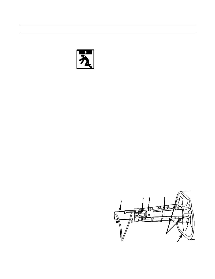
4.
Install two adapters (12) into large threaded holes in
5
bevel gear case (8).
14 13
15
5.
Install adapter (13) on end of sprocket shaft (5) and
connect rod (14) to adapter.
6.
Connect hydraulic cylinder (15) to adapters (12) in
bevel gear case (8).
NOTE
Maintain force on sprocket shaft (5) while
12
installing and applying torque to nut (3).
7.
Attach hydraulic pump to hydraulic cylinder (15).
387-614
8
Apply 55-60 tons (490-535 kn) of force to push
sprocket shaft (5) into position,
0142 00-4
|
|
Privacy Statement - Press Release - Copyright Information. - Contact Us |
