 |
|||
|
|
|||
|
|
|||
| ||||||||||
|
|
 TM 5-2410-237-23
TORQUE DIVIDER REPLACEMENT - CONTINUED
0115 00
INSTALLATION - CONTINUED
WARNING
Use extreme caution when handling heavy parts. Provide adequate support and use assistance during pro-
cedure. Ensure that any lifting device used is in good condition and of suitable load capacity. Keep clear of
heavy parts supported only by lifting device. Failure to follow this warning may result in death or injury to
personnel.
NOTE
Torque divider weighs 300 lb (136 kg).
6.
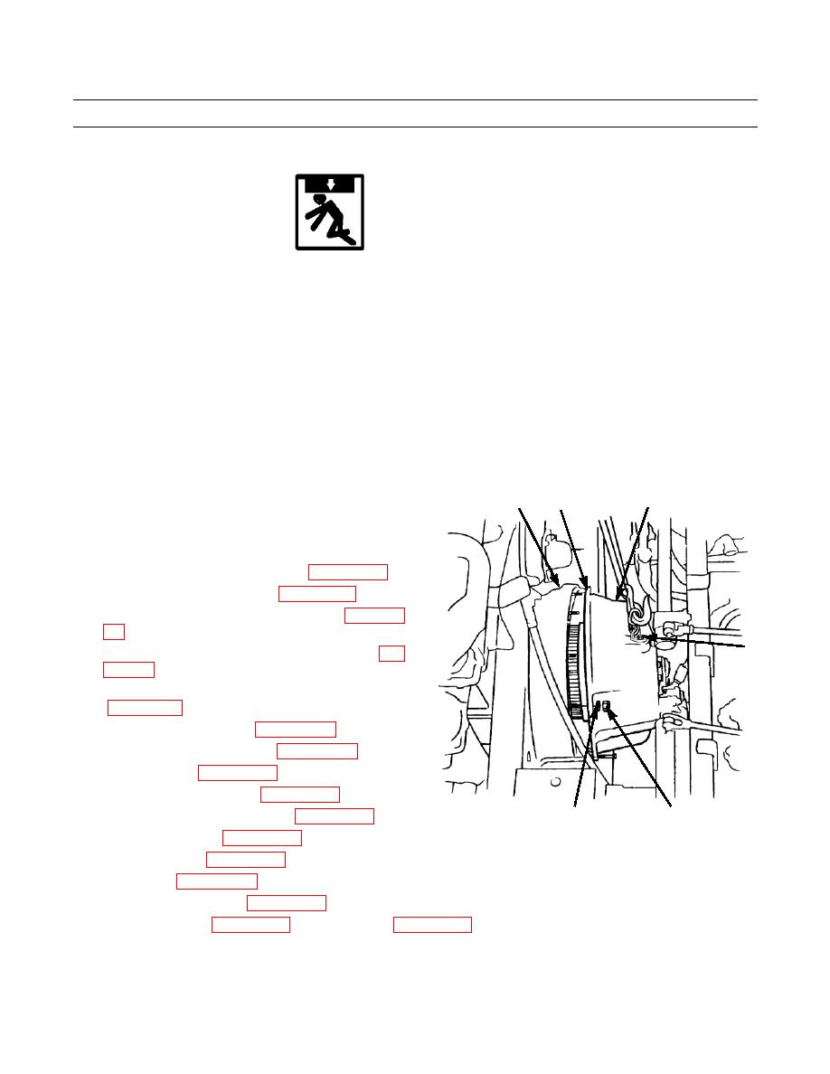
Fasten a nylon sling and a suitable lifting device to lifting links (1) and carefully lift torque divider (2) into position.
7.
Slide torque divider (2) onto studs on flywheel housing (6). Remove wire.
NOTE
Carefully maneuver torque divider onto flywheel housing so that planetary gears engage with flywheel.
8.
Install 12 new lockwashers (4) and nuts (3). Tighten
2
6
14
nuts to 75 lb-ft (102 Nm).
9.
Remove lifting equipment, two bolts and lifting links
(1) from top of torque divider (2).
10.
Install torque divider scavenge pump (WP 0121 00).
11.
Install transmission relief valve (WP 0119 00).
12.
Install torque converter outlet relief valve (WP 0120
1
13.
Connect transmission oil lines to torque divider (WP
14.
Connect transmission oil cooler lines to torque divider
15.
Connect brake lock linkage (WP 0149 00).
16.
Connect steering clutch linkage (WP 0148 00).
17.
Install driveshaft (WP 0129 00).
18.
Install brake pedal assembly (WP 0146 00).
387-753
3
4
19.
Install seat and seat base assembly (WP 0172 00).
20.
Install dash assembly (WP 0160 00).
21.
Install floor plates (WP 0171 00).
22.
Install ROPS (WP 0164 00).
23.
Install transmission guard (WP 0157 00).
24.
Refill torque divider (WP 0106 00) and transmission (WP 0107 00).
25.
Run engine and test drive in all speeds.
END OF WORK PACKAGE
0115 00-4
|
|
Privacy Statement - Press Release - Copyright Information. - Contact Us |