 |
|||
|
|
|||
|
Page Title:
STEERING BRAKE PEDALS AND LINKAGE MAINTENANCE |
|
||
| ||||||||||
|
|
 TM 5-2410-237-23
STEERING BRAKE PEDALS AND LINKAGE MAINTENANCE
THIS WORK PACKAGE COVERS
Removal, Disassembly, Assembly, Installation
INITIAL SETUP
Tools and Special Tools
References
TM 5-2410-237-10
Tool kit, general mechanic's (Item 122, WP 0250
Equipment Condition
Shop equipment, common no.1 (Item 103, WP
Battery cables disconnected (WP 0101 00)
Floor plates removed (WP 0171 00)
Materials /Parts
Seat and seat base removed, if replacing rearmost
Key (34)
linkage at brake actuating mechanism
Lockwasher (2, 15, 20 and 28)
Fuel tank removed, if replacing rearmost linkage at
brake actuating mechanism (WP 0052 00)
Pin, cotter (6, 11 and 23)
REMOVAL
WARNING
Ensure battery cables are disconnected before performing maintenance inside dash assembly. Failure to
follow this warning could result in injury or damage to equipment.
NOTE
5
1, 2, 3
This procedure to be used for R.H. or L.H.
brake linkages.
1.
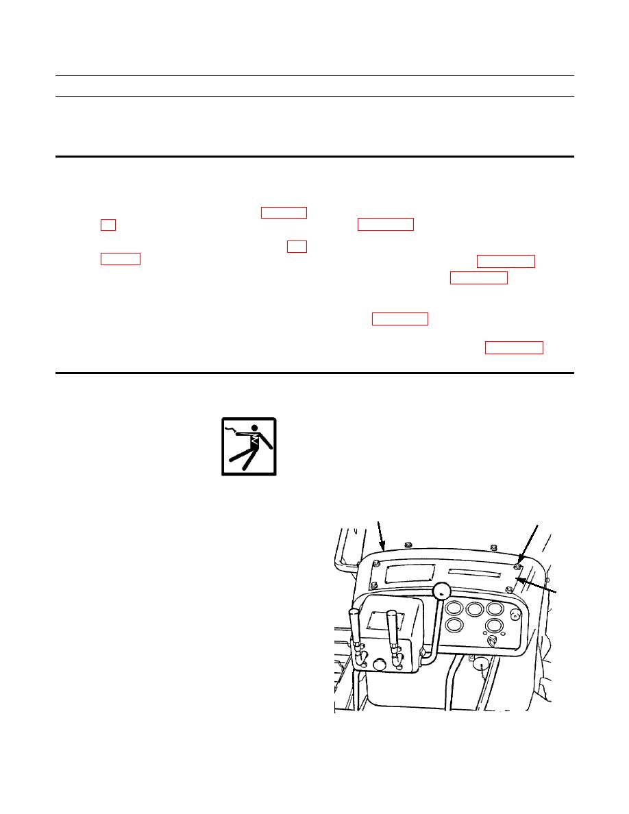
Remove four capscrews (1), lockwashers (2), washers
(3) and cover (4) from top of dash assembly (5). Dis-
card lockwashers.
4
387-045
|
|
Privacy Statement - Press Release - Copyright Information. - Contact Us |