 |
|||
|
|
|||
|
Page Title:
TRANSMISSION OIL COOLER LINES REPLACEMENT |
|
||
| ||||||||||
|
|
 TM 5-2410-237-23
TRANSMISSION OIL COOLER LINES REPLACEMENT
THIS WORK PACKAGE COVERS
Removal, Installation
INITIAL SETUP
Tools and Special Tools
Materials/Parts - Continued
Rag, wiping (Item 29, WP 0249 00)
Tool kit, general mechanic's (Item 122, WP 0250
Lockwasher (2, 8, 17, 27 and 31)
Shop equipment, common no. 1 (Item 103, WP
O-ring (9, 10, 18, 19, 24, 25, 29 and 32)
Equipment Condition
Materials/Parts
Floor plates removed (WP 0171 00)
Cap set, protective (Item 2, WP 0249 00)
Transmission oil drained (WP 0107 00)
Seat with vertical adjuster removed (WP 0172 00)
Oil, lubricating (Item 23, 24, 25 or 26, WP 0249 00)
REMOVAL
1.
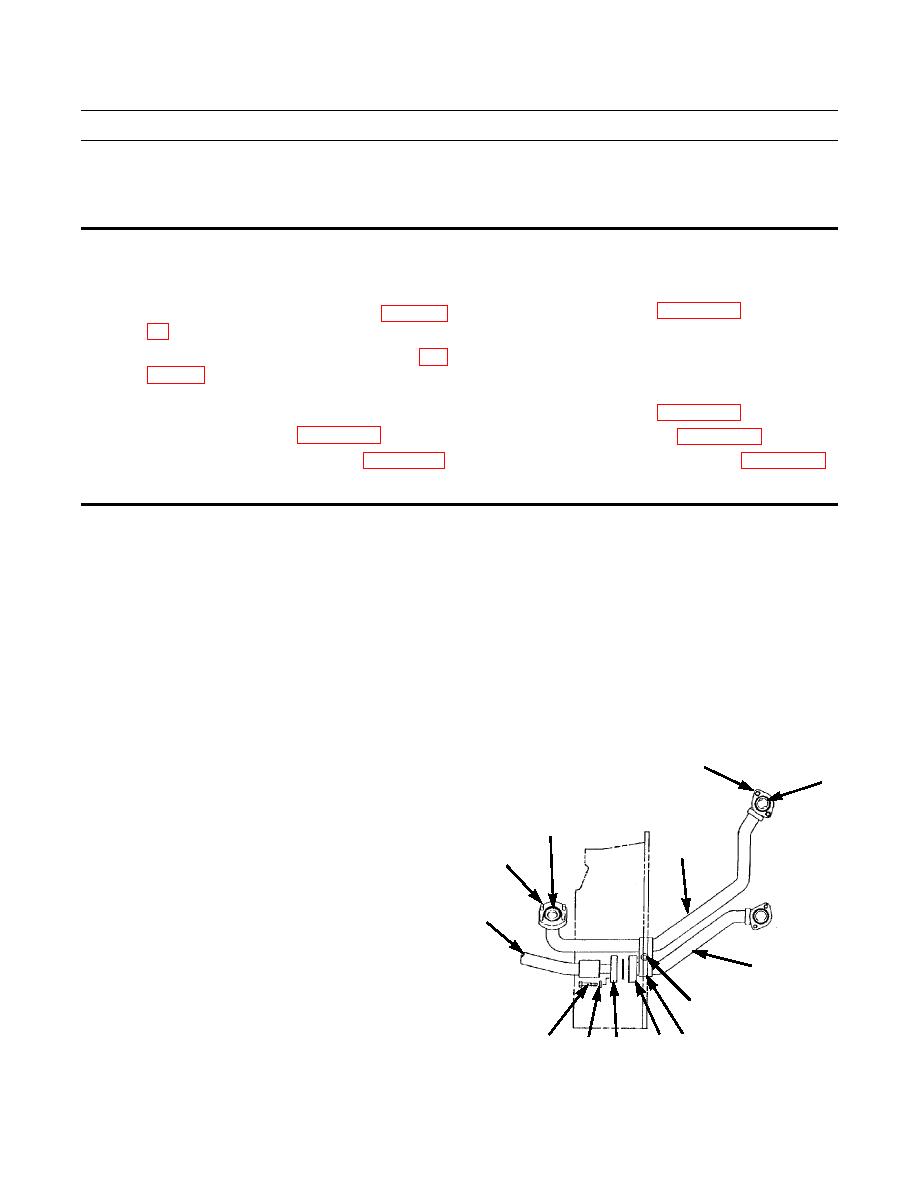
Loosen capscrew (1), lockwasher (2), nut (3) and clamp set (4).
CAUTION
Place protective caps on all transmission system openings to prevent foreign materials from contaminating
system.
NOTE
Use a suitable container to capture residual draining oil when disconnecting oil cooler lines. Dispose of oil
IAW local policy and ordinances. Ensure all spills are cleaned up.
2.
Remove four capscrews (5) holding tube assembly (6)
7,8
10
to torque converter outlet relief valve.
3.
Remove two capscrews (7) and lockwashers (8) hold-
ing tube assembly (6) to oil cooler inlet. Separate tube
9
assembly from outlet relief valve and oil cooler inlet.
6
Lift out tube assembly. Remove O-rings (9 and 10)
5
from ends of tube assembly. Discard lockwashers and
O-rings.
14
4.
Remove four capscrews (11), washers (12) and two
flange halves (13) holding hose assembly (14) to
cooler line tube assembly (15).
15
1,2,3
387-371
11
13 4
13
12
|
|
Privacy Statement - Press Release - Copyright Information. - Contact Us |