 |
|||
|
|
|||
|
|
|||
| ||||||||||
|
|
 TM 5-2410-237-23
VALVE MECHANISM ADJUSTMENT- CONTINUED
0018 00
ADJUSTING VALVE CLEARANCE - CONTINUED
2.
After each adjustment has been made for a specific valve, tighten nut (5) for valve adjustment screw (6) to 22 lb-ft (30
Nm), while holding screws.
NOTE
Set all valves that need adjustment to 0.025 in. (0.64 mm) for exhaust and to 0.015 in. (0.38 mm) for intake
in the following manner.
3.
With engine set with number 1 piston at TDC on compression stroke, make adjustments for valve clearance on intake
valves for cylinders 1, 2 and 4. Make an adjustment to valve clearance on exhaust valves for cylinders 1, 3 and 5.
4.
Remove bolt (3) from flywheel housing and turn flywheel 360 degrees to the right. This will put number 6 piston at
TDC on compression stroke. Install bolt back into flywheel housing.
5.
Make an adjustment to valve clearance on intake valves for cylinders 3, 5 and 6. Make an adjustment to valve clearance
on exhaust valves for cylinders 2, 4 and 6.
CAUTION
Bolt will damage flywheel housing and flywheel if not removed and replaced by plug.
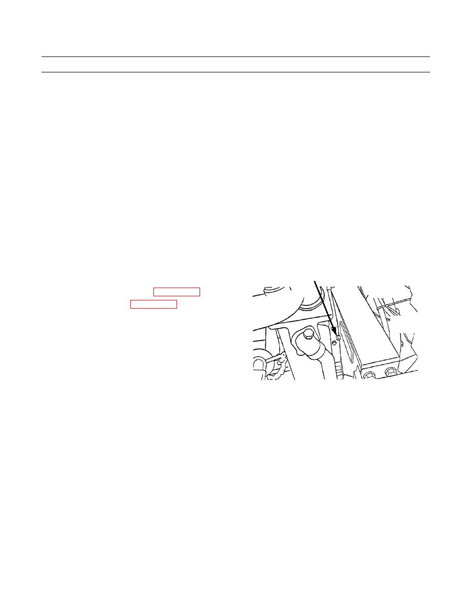
6.
Remove bolt (3) and install plug (1) in flywheel hous-
1
ing.
7.
Install valve mechanism cover (WP 0017 00).
8.
Install crankcase guard (WP 0157 00).
387-121
END OF WORK PACKAGE
0018 00-3
|
|
Privacy Statement - Press Release - Copyright Information. - Contact Us |
