 |
|||
|
|
|||
|
Page Title:
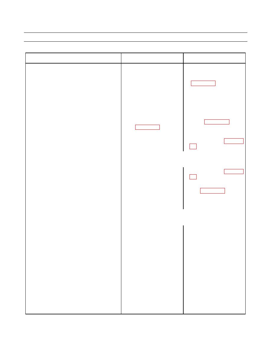
Table 6. Electrical System Troubleshooting Procedures - Continued. |
|
||
| ||||||||||
|
|
 TM 5-2410-237-23
TROUBLESHOOTING PROCEDURES - CONTINUED
0006 00
Table 6. Electrical System Troubleshooting Procedures - Continued.
MALFUNCTION
TEST OR INSPECTION
CORRECTIVE ACTION
1. If battery voltage is not
10. No Alternator Output - Continued.
d. Place battery disconnect
indicated, repair or replace
switch to ON position and
alternator-to-ammeter wiring
observe
reading.
e. If battery voltage is
indicated, place battery
disconnect switch in OFF
position.
f. Check continuity between
1. Repair or replace alternator
alternator and ground
ground (WP 0242 00).
2. If wiring to ground is OK,
replace alternator (WP 0076
NOTE
11. Alternator Output Low (Ammeter Reading
in Red Zone).
If STE/ICE is available, perform TK Mode, NG50.
1.
Check for loose, broken or
1. Adjust loose belts (WP 0074
missing alternator belts.
2. Replace broken or missing
belts (WP 0074 00).
2.
Test charging voltage. Go to
Table 6, Malfunction 7.
NOTE
12. Alternator Charge Too High (Ammeter in
High Green Zone).
If STE/ICE is available, perform TK Mode, NG50.
1.
Test charging voltage. Go to
Table 6, Malfunction 7.
2.
Check
alternator
for
overheating.
a. Run
engine
for
approximately
10
minutes.
If alternator is hot, place battery
b. With engine off, check
disconnect switch to OFF
alternator
for
high
position and allow alternator to
temperature by holding
cool.
hand near alternator.
Change 1
|
|
Privacy Statement - Press Release - Copyright Information. - Contact Us |