 |
|||
|
|
|||
|
|
|||
| ||||||||||
|
|
 (2) Inspect the roller sleeve bearings for
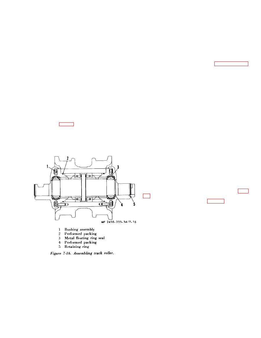
(1) Install the preformed packing (2) on the
bushing (1) and remove any burrs from the roller to
pitting, roughness, and wear. The specified shaft to
bearing clearance i s 0.008-0.012 inch. The
prevent damage to the preformed packing.
maximum allowable shaft to bearing clearance is
NOTE
0.050 inch. The specified shaft end clearance is
White lead should be used on the outside diameter of
the bushing assembly when pressing it into place.
0.011-0.029 inch. The maximum allowable shaft
end clearance is 0.050 inch. Replace pitted, rough,
(2) Install the shaft before pressing in the
or excessively worn bearings.
second bushing.
(3) Inspect the roller shaft for pitting,
(3) Install the metal floating ring seals (3) in
roughness, wear, and distortion. The maximum
the roller and collars as outlined in paragraph 6-22.
allowable bend in roller shaft is 0.005 inch.
(4) Install the preformed packing (4) on the
Replace a damaged, excessively worn, or bent roller
track roller shaft and lubricate it to facilitate in-
shaft.
stallation of the end collar.
(4) Inspect the metal floating ring seals for
(5) Remove any burrs, smooth the chamfer in
damage and proper wear pattern. Replace seals
the bore of the end collar and install the end collar
which are pitted, grooved, scratched across the seal
and the retaining ring (5).
surface, or which show an uneven wear pattern.
(6) Lubricate the roller.
Seals must be replaced in sets.
f. Installation.
e. Assembly.
(1) Install the track roller with notched end
collar toward the center of the tractor.
NOTE
Care should be taken when pressing tbe bushing
(2) Place the roller assemblies on the track in
assembly (1, fig. 7-16) into place to see that the bolt
the proper relative locations and follow the reverse
holes in the bushing flange are held in alignment with
order of removal in completing the installation.
the holes in the roller hub. This can be done by
(3) Place the wedge-shaped lock strip in the
screwing three studs 120 apart into the roller hub to
notch in the end of the shaft and in the notch of tbe
act as guides.
end collar and securely tighten the bolts which hold
the end collars to the track roller frame. Some
clearance will remain between the track roller
frame and the end collars to insure that the ends of
the track roller shaft will be held securely against
the track roller frame.
7-4. Front Idler
a. Removal.
(1) Separate the track and lay it out flat (para
(2) Remove the guard (1, fig. 7-17) bolts (2),
and guide plate (3).
NOTE
Keep the shims from beneath guide plate (3) together.
The same shims will be used for assembly. The
following removal procedure is applicable to both sides
of the idler and for both front track idlers.
|
|
Privacy Statement - Press Release - Copyright Information. - Contact Us |