 |
|||
|
|
|||
|
|
|||
| ||||||||||
|
|
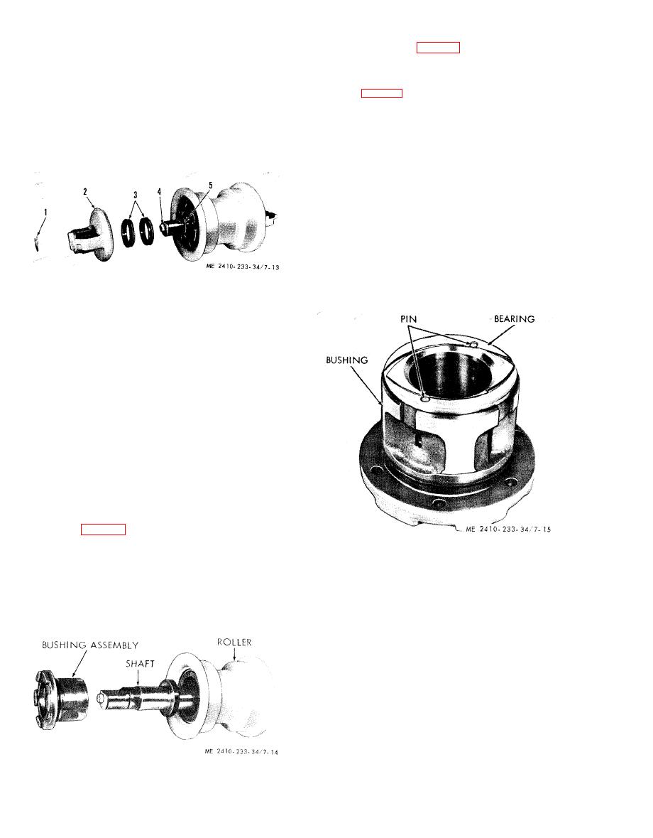 (6) The bearing (fig. 7-15) can be pressed out
NOTE
and replaced provided the bushing is not damaged.
To facilitate removal of the front or rear rollers, the
second roller from either end should be removed and
NOTE
rolled back on the rails out of the way.
Install new bearings if the shaft clearance exceeds that
given in table 1-5.
CAUTION
Do not extend any part of body, legs or
(7) Press the bearing out of the bushing and
arms, between the track and rollers, or
cut off the projecting pins with a hacksaw.
between ground and track during
(8) Smooth the face of bushing with a file.
removal of lower track rollers.
(9) Press the new bearing into place making
certain the lubricant holes are aligned.
(10) Drill two 9/32 inch holes 13/16 inch
deep through the flange of the bearing and into the
wall of the cast iron bushing.
CAUTION
Be sure the holes do not interfere with
lubrication grooves in the face of the
bearing flange.
(11) Install the proper pins so they do not
extend above the face of the bearing.
(12) Smooth the face of the bearing flange.
1
Ring
2
Collar
3
Metal floating ring seals
4
Plug
5
Preformed packing
b. Disassembly.
(1) Remove the ring (1).
(2) Remove the collar (2), the metal floating
ring seals (3), the plug (4) and the preformed
packing ( 5).
CAUTION
The two metal floating ring seals (3)
should be taped together so they will
not become intermixed with seals from
other rollers.
(3) The other end of the roller is disassembled
in the same manner.
(4) Remove the bolts which secure the bushing
assembly (fig. 7-14) to the roller.
(5) The bushing assembly can be pressed out
of the roller by supporting the roller and pressing
c. Cleaning.
on the end of the shaft. The bushing assembly can
(1) Clean all parts using cleaning solvent (Fed.
then be removed from the shaft. Insert the shaft
Spec. P-D-680) and wipe dry with a lint-free cloth.
back into roller and repeat the procedure to press
(2) Remove all dirt and rust from the floating
the bushing assembly from the-opposite end.
ring seal mounting grooves. Grooves must be clean,
smooth and dry.
(3) Wash protective coating from new ring
seals with cleaning solvent.
d. Inspection and Repair.
(1) Inspect the track rollers for damage and
wear. When the contact surface of the roller is worn
from 8.38 to 8.00 inches in diameter, the roller will
be repaired by welding an overlay on the wear
surface. Rollers worn to a diameter of 8.00 inches
or less, or rollers uneconomical to repair, will be
replaced. The diameter of a new roller is 8.75
inches.
|
|
Privacy Statement - Press Release - Copyright Information. - Contact Us |
