 |
|||
|
|
|||
|
Page Title:
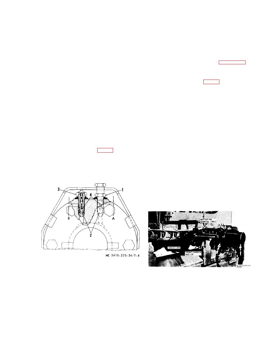
Figure 7-4. Relief valve and fill valve. |
|
||
| ||||||||||
|
|
 (6) Loosen fill valve (3) until the unthreaded
WARNING
section (B) is exposed above the flange of the
Because of the hydraulic pressure in the
hydraulic cylinder. The hexagonal shoulder of fill
track adjuster cylinder, never visually
valve (3) will contact the underneath side of the
inspect the vent holes and valves to see
guard. Grease should then escape through slot (4)
if grease is escaping. Always observe the
in the lower section of the threads.
cylinder to see that it moves to the rear
into the recoil spring front pilot.
NOTE
(4) Turn relief valve one turn in a coun-
Detailed information concering the hydraulic track
terclockwise direction and allow grease to escape
adjusting mechanism can be found in paragraph 7-7.
from vent hole just below relief valve. If grease does
(7) Position the master pin above and slightly
not appear when the relief valve is backed off one
behind the front carrier roller.
turn, turn fill valve one turn in a counterclockwise
(8) Install the tools (fig. 7-5) and press the
direction. If grease does not appear at the vent
master pin from the links.
holes, the machine should be started and moved
forward and backward. If grease still does not
NOTE
appear at the vent holes, insert a bar (such as a
An alternate method for master pin removal is as
draw bar pin) between the track and sprocket.
follows: Place a block approximately 12 inches high in
front of the track and drive the machine forward so the
Move the machine backward so the track will be
track shoe below the master pin rides on the block,
forced upward by the bar. This will apply ad-
then using a suitable drive and a sledge hammer, drive
ditional tension to the track and move the front
the master pin out of the links.
idler and track adjusting mechanism to the rear
against tie force of the recoil springs, thus forcing
grease out the vent holes.
(5) If moving the machine does not relieve the
hydraulic pressure, continue loosening relief valve
until the unthreaded section (A, fig. 7-4) is exposed
above the flange of the hydraulic cylinder. The
lower hexagonal shoulder of the relief valve will
contact the underneath side of the guard. Grease
should then escape through slot (4) in the lower
section of threads.
1
Relief valve
2
Vent holes
3
Fill valve
4
Slots
A
and B-Unthreaded sections
|
|
Privacy Statement - Press Release - Copyright Information. - Contact Us |
