 |
|||
|
|
|||
|
|
|||
| ||||||||||
|
|
 worn track, it is possible for the
hydraulic track to be adjusted forward
to the limit of its travel and the stop will
he against the equalizer bar support.
The hydraulic cylinder could have high
oil pressure in it even though the track
is loose enough to remove the master
p i n without relieving the hydraulic
track adjusting pressure.
(1) Separate the track and lay it out flat (para
(2) Remove guards (fig. 7-25).
(3) Remove either carrier roller support
assembly (para 7-8) or recoil spring assembly (para
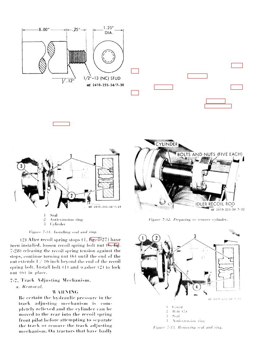
(4) Remove bolts and nuts (fig. 7-32).
e. Installation.
( 5 ) Remove the seal (3, fig. 7-33) and
(1) Install the recoil spring assembly in reverse
antiextrusion ring (4).
order of removal.
NOTE
NOTE
When installing (2, fig. 7-31), in cylinder (3), the
When installing antiextrusion ring (4), place the
beveled edge is placed toward the cylinder. Align the
beveled edge toward the cylinder.
flat on the cylinder flange with the flat (or guard) on
the idler recoil rod flange.
|
|
Privacy Statement - Press Release - Copyright Information. - Contact Us |
