 |
|||
|
|
|||
|
|
|||
| ||||||||||
|
|
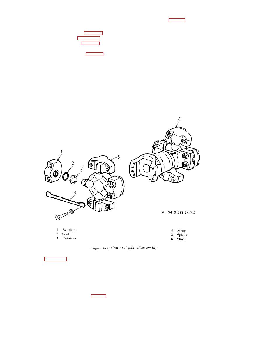 b. Disassembly (fig. 6-3).
6-2. Universal Joint
secure
the
(1) Remove the bolts
which
a. Removal.
b e a r i n g s to the spiders.
(1) Remove the floor plates (para 2-8a) and
( 2 ) Remove the strap (4) from bearings (1).
the brake pedals and support (para 6-30).
(3) Remove the bearing (1), seal (2) and
( 2 ) Remove oil supply line (fig. 2-33), (sheet
retainer (3) from the spider (5).
2 ) and oil pressure line.
c.
Inspection.
( 3 ) Rotate the universal joint (fig. 2-31, sheet
(1) Inspect the spider journal bearing surfaces
4 of 6) as necessary and remove the bolts securing
f o r roughness or needle bearing grooves.
the bearing caps to the transmission input shaft
(2) Carefully inspect each bearing for wear
f l a n g e and torque divider output shaft flange.
a n d for broken or missing needle bearings.
( 4 ) Pry the universal joint bearing caps loose
( 3 ) Replace the spider and bearing assembly
f r o m each flange and remove the universal joint.
wear.
NOTE
Do
not
cut
the
metal
straps
securing
the
bearing
( 4 ) Light brineling of the spider bearing area
caps
to
the
spider.
If
they
are
cut
or
missing,
tem-
is not harmful.
porarily fasten the bearing caps to the wniversal joint to
d. Reassembly and Installation. Reassemble the
prevent
them
from
sliding
off
or
dirt
entering
the
universal joint in the reverse order of disassembly.
bearings.
stator or reactionary member (12) which directs the
Torque
Divider
o i l to rotate the turbine (10). Since the turbine is
a. General (fig. 6-1). The torque divider is
mounted in the torque divider housing (1). It pilots
s p l i n e d to the same hub) as the ring gear (4), the
into the diesel engine flywheel (3) and is supported
torque, is transferred through the planet carrier (8)
in the housing (1) by a bearing mounted in a carrier
to the output shaft (7). A lesser amount of torque is
t r a n s m i t t e d from the engine flywheel (3) through
(11).
the sun gear (6) and planet carrier (8) to the output
b. O p e r a t i o n .
shaft (7).
( 1 ) The torque divider is driven by the diesel
emgine through a rotating housing (2, fig. 6-1) and
(2) The planetary system is composed of a sun
sun gear (6) to direct the torque output of the
gear (6) that turns with the diesel engine flywheel
engine through two separate paths. Most of the
(3), a planet carrier (8) which is splined to the
t o r q u e is transmitted by the rotating housing (2)
o u t p u t shaft (7) and supports the planet gears (9)
and impeller (5) through a medium of oil to the
t h a t mesh with the ring gear (4).
|
|
Privacy Statement - Press Release - Copyright Information. - Contact Us |
