 |
|||
|
|
|||
|
Page Title:
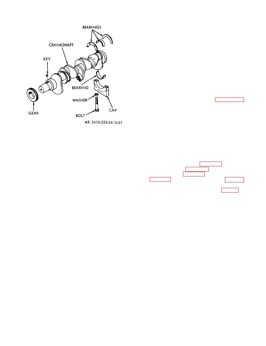
Figure 5-57. Crankshaft and main bearings. |
|
||
| ||||||||||
|
|
 inch. At installation use undersize main and
connecting rod bearings.
(3) After grinding, clean the crankshaft
thoroughly. Check for runout with a dial indicator.
If crankshaft runout exceeds 0.008 inch, replace
the crankshaft.
(4) Inspect the crankshaft gear for cracks,
broken teeth, burrs, scoring and wear. Remove
burrs and light scoring with a soft hone or crocus
cloth or replace the gear if necessary.
d. Reassembly.
(1) Position the key in the crankshaft. Using a
hydraulic pump, press the crankshaft gear onto the
crankshaft.
(2) Install the crankshaft in the block. Align
the crankshaft gear as instructed in paragraph 5-
29.
(3) Install the bearing liners and lubricate the
inside surfaces of the bearings. Rotate the upper
bearings into position in the reverse order of
removal. Ensure that bearings are installed in the
same positions they were removed from.
(4) Install the lower bearing caps and secure
(8) Grasp the bearing cap at the recessed
with nuts. Tighten the nuts to a torque of 155 foot-
portion and pull outward. Tap the cap lightly with
pounds.
a soft hammer to aid in removal.
(5) Check the bearing clearance (subpara e)
and the crankshaft end clearance (subpara f).
NOTE
M a r k the upper and lower caps for location.
(6) Install the oil pump (para 5-24) and oil
pan and oil pan plate (para 5-25). Install the
(9) Place a main bearing removal tool in the
flywheel and housing (para 5-32) and timing gear
drilled oil hole of the crankshaft journal. Rotate the
cover (para 5-29). Install the water pump (para 5-
crankshaft and roll out the bearing upper half. Roll
6).
out the bearing tab end first. Remove the liners
(7) Install the engine in the tractor (para 2-8).
from the bearings.
e. Main Bearing Clearance Check.
(10) Cover the bearing cap studs with rubber
hose or cloth to protect the crankshaft when it is
NOTE
removed.
If bearing clearance is checked while the crankshaft is
(11) Lift the crankshaft from the engine.
installed and the engine is upright, hold the crankshaft
Lubricate and wrap the bearing surfaces.
against the upper halves of the bearings.
(12) Using a hydraulic puller, pull the
(1) Place a soft lead wire between the lower
crankshaft geat from the crankshaft. Remove the
bearing half and the crankshaft. Coat two 1-inch
key.
lengths of the wire with grease and place them
b. Cleaning. Clean the crankshaft and bearings
diagonally on the bearing. The grease will hold the
with cleaning solvent (Fed. Spec. P-D-680) and dry
wires in position.
with clean, lint-free cloths. Clean the oil holes in the
( 2 ) Turn the crankshaft one complete
block and ensure that the block is clean.
revolution.
c. Inspection and Repair.
(3) Remove the bearing cap and measure the
(1) Insect the bearing caps for burrs and
thickness of the compressed wire u s i n g a
high spots. Smoot surfaces with a soft hone or
micrometer. Clearance should be 0.0030 to 0.0059
crocus colth. Scratches on the bearig surfaces will
inch. Replace bearings if the proper clearance is not
not impair operation. Replace beaings if the
obtained.
surface is excessively rough and abrasive. If one
f. Crankshaft End Clearance Check.
bearing is replace, replace all bearings if possible.
(1) Push the crankshaft as far as it will go to
(2) Check the main bearing journals with a
one end of the cylinder block.
micrometer for out-of-round condition or excessive
( 2 ) Using a thickness gage, measure the
wear. If crankshaft journals are worn more than
c l e a r a n c e between the machined face of the
0.008 inch, g r i d the journals with precision
crankshaft flange and the flange of the lower half of
equipment, checking diameter frequently with a
micrometer. Grind the journals undersize 0.030
|
|
Privacy Statement - Press Release - Copyright Information. - Contact Us |