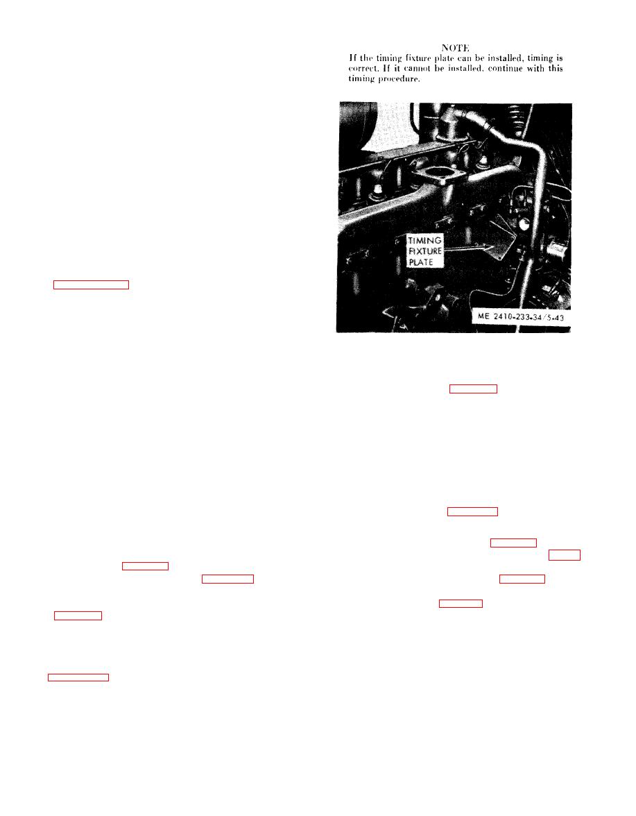
 |
|||
|
|
|||
|
|
|||
| ||||||||||
|
|
 (4) Position the accessory drive gear to allow
access to the bolts which secure the accessory drive
housing to the timing gear plate. Remove the bolts
and locks.
CAUTION
Do not allow the bolts or locks to fall
into the timing gear housing.
( 5 ) Remove the accessory drive gear retaining
nut.
(6) Install puller and push the accessory drive
s h a f t until the gear comes off the shaft and the
accessory drive is removed from the timing gear
housing.
( 7 ) Pull the bearing from the shaft.
(8) Discard the housing mounting gasket.
b. Cleaning, Inspection and Repair.
(1) Clean the shaft, cover and gear in solvent
a n d dry with clean, l i n t - f r e e cloths or with com-
pressed air. Clean the bearing as instructed in
( 2 ) Inspect the gear for broken, damaged or
m i s s i n g teeth. Replace as necessary.
(3) Inspect the shaft for damage, distortion
a n d wear. Inspect the bearing contact surface for
u n e v e n or excessive wear. Repair as required.
c. I n s t a l l a t i o n .
( 1 ) Press the bearing onto the shaft. Install
(3) Remove the small cover from the front of
t h e bearing retaining plate.
the timing gear housing (fig. 5-42). Remove the
(2) Install the drive shaft into the timing gear
a c c e s s o r y drive gear retaining nut and washer.
housing.
(4) Separate the gear from the accessory drive
CAUTION
shaft.
Do not allow the bearing retaining plate
(5) Rotate the accessory drive shaft as
to fall into the timing gear housing
necessary to permit installation of the timing fixture
when installing the drive shaft.
plate.
(3) Time the accessory drive shaft (subpara
(6) Insert the shaft through the gear. Tighten
d).
the gear retaining nut to a torque of 90 to 110 foot-
(4) Install the gear and secure with the
pounds and remove the timing plate. Install the fuel
retaining nut. Tighten the nut to a torque of 90 to
injection pump housing (para 5-11).
110
foot-pounds.
5-29. Timing Gears and Cover
( 5 ) Install the accessory drive housing to the
t i m i n g gear plate and secure with bolts and locks.
a. Removal and Disassembly (fig. 5-44).
(6) Install the fuel injection pump housing
a n d governor (para 5-11). Install the fuel transfer
2-8), and block in position.
(2) Remove the water pump (para 5-6), and
pump and fuel filter housing (para 5-13).
d. Timing.
generator as instructed in TM 5-2410-233-20.
(1) Remove the fuel injection pump housing
Remove the fan belts (para 5-5).
( p a r a 5-11) and position the engine crankshaft so
(3) Loosen the bolt (1) approximately five
that the No. 1 piston is at top dead center (TDC) of
turns.
compression stroke.
(4) Using a hydraulic puller, pull the
( 2 ) Install a timing fixture plate on the rear
crankshaft pulley assembly from the crankshaft.
face of the accessory drive housing as shown in
|
|
Privacy Statement - Press Release - Copyright Information. - Contact Us |
