 |
|||
|
|
|||
|
Page Title:
Fuel Injection Pump |
|
||
| ||||||||||
|
|
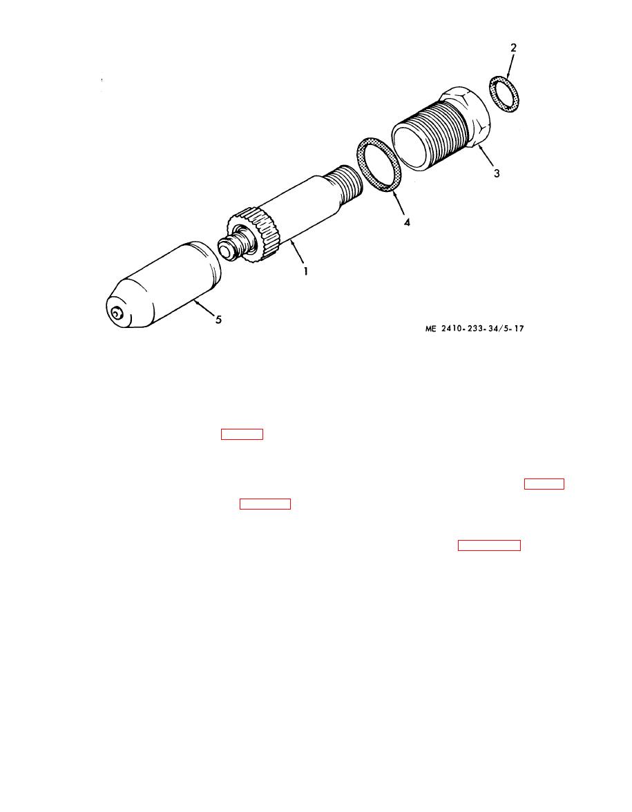 1
Body
2
Seal
3
Nut
4
Seal
5
Nozzle
(4) Connect the fuel line (fig. 5-16).
(3) Each pump measures the amount of fuel
to be injected into the cylinder and delivers it to the
(5) Bleed the fuel system as instructed in TM
fuel injection nozzle in the precombustion chamber.
5-2410-233-20.
(4) The amount of fuel pumped per stroke is
5-11. Fuel Injection Pump
varied by the turning of the plunger (9, fig. 5-19) in
a. General.
the pump barrel (6). The plunger is turned by
(1) The fuel injection pump (fig. 5-19) is
governor action through the circular rack (12)
composed of six individual pumps installed in the
which turns the gear segment on the bottom of the
fuel injection pump housing.
pump plunger (9).
(2) The pump is camshaft operated and
driven by an adapter from the accessory drive shaft.
(1) Disconnect the linkage at the governor
Fuel enters the fuel injection pump housing
control lever.
through an inlet port from the fuel filter. The pump
(2) Disconnect the fuel injection lines at the
plungers and lifters are actuated by lobes on the
housing. Cap or plug openings.
pump camshaft. The lifters are held against the
cam lobes by springs.
|
|
Privacy Statement - Press Release - Copyright Information. - Contact Us |
