 |
|||
|
|
|||
|
|
|||
| ||||||||||
|
|
 (5) Rotate the crankshaft in its direction of
dividual fuel pumps and add spacers below the
normal rotation from 30 before top dead center
lifters as necessary to adjust timing.
until the inlet port closes. At this point fuel flow is
k. Setting Fuel Rack.
(1) Remove the rack cover from the front of
reduced to 6 to 12 drops per minute. Zero the dial
the accessory drive housing rear flange (para 5-28).
indicator.
Remove the cover from the rear of the governor
(6) Rotate the crankshaft until the indicator
housing (para 5-10).
reaches maximum value. At this point the piston is
(2) Install a rack setting gage over the front
at top dead center.
end of the fuel rack.
(7) At proper timing, the indicator reading
should be 0.1091 (+0.0040) inch.
(3) Loosely install a plug and push rod in the
governor plug (59, fig. 5-20) hole. Force the speed
i. Checking Fuel Injection Pump Timing (On
limiter away from the plug hole.
Engine, Using a Gage).
(4) Move the governor control lever forward
(1) Locate the top dead center compression
until the stop collar on the fuel rack just touches the
position for the No. 1 piston.
stop bar on the torque spring. If necessary, insert a
(2) Remove the No. 1 fuel injection pump
(subpara c above). Insert a timing gage, into the
0.003 inch feeler gage between the stop and spring
fuel pump bore.
to help determine the point of contact.
(3) Ensure that the higher step of the pump
plunger is slightly above the top surface of the gage
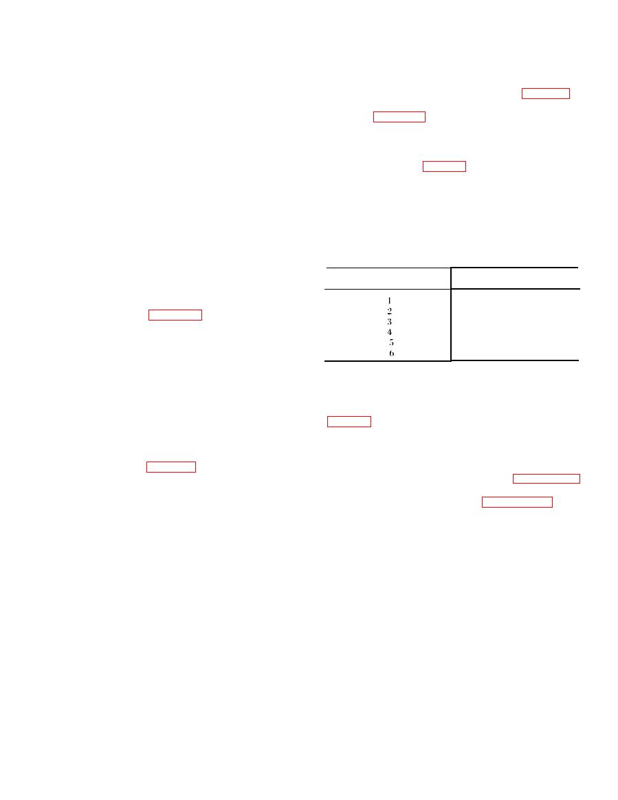
Lifter number
Timing plate
body and that the lower step of the plunger is just
degrees
below the top surface of the gage body. If the gage
179
30'
cannot be correctly positioned, check accessory
59
30'
drive shaft timing (para 5-28).
299
30'
(4) If the gage is correctly installed, the fuel
119
30'
pump is correctly timed.
239 30'
359 30'
j. Setting Fuel Injection Pump Timing (Off
Engine).
(5) Position the rack setting gage from the
NOTE
zero position until it contacts the rack. Total rack
The fuel pump can be adjusted while removed from
travel should be 0.650 inch.
the engine.
(6) To adjust the rack, loosen the locknut (37,
(1) Install a pointer on tbe fuel injection
pump housing.
obtain the desired setting. Tighten the locknut.
(2) Place the timing plate on the drive end of
5-12. Engine Speed Governor
the camshaft and secure.
a. Removal. Remove the engine speed governor
(3) Refer to table 5-1 and select the timing
with the fuel injection pump. Refer to paragraph 5-
plate degree setting for the lifter to be set. Set the
11.
lifter to be set. Set the timing plate by rotating it
b . Disassembly. Refer to figure 5-20 and
counterclockwise until the proper degree setting
disassemble the governor according to sequence of
aligns with the pointer. Lock in position with the
index numbers assigned to figure.
setscrew.
(4) The fuel injection pump timing dimension
is 4.267.5 (+0.0005) inches. Remove the in-
|
|
Privacy Statement - Press Release - Copyright Information. - Contact Us |
