 |
|||
|
|
|||
|
Page Title:
Section II. FUEL SYSTEM |
|
||
| ||||||||||
|
|
 Section II. FUEL SYSTEM
5-9. General
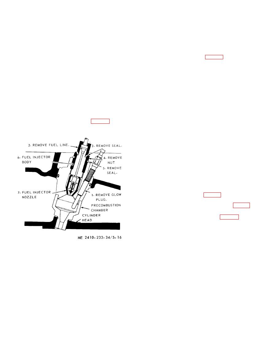
(2) Tag and disconnect electrical lead and
remove glow plug from precombustion chamber.
The fuel system consists of a supply tank, fuel
injection valves, fuel injection pump, pressure gage,
(3) Remove the nut securing the nozzle and
body in the precombustion chamber.
fuel filters, transfer pump, vent valve and primer
pump. The transfer pump draws fuel from the fuel
(4) Lift out the nozzle (5, fig. 5-17) and body
tank and delivers the fuel through the primary and
(1) and discard the two seals (2 and 4).
secondary fuel filters to the fuel injection pump.
(5) Unscrew the nozzle (5) from the body (1).
The injection pump delivers the fuel under high
b. Cleaning. Clean the fuel discharge hole in the
nozzle. Remove any carbon deposits.
pressure to the injection valves, where it is sprayed
c. Repair. Inspect the nozzle for an ac-
into the engine precombustion chambers. The
accessory drive shaft drives the governor, fuel
cumulation of carbon, eroded orifice and plugged
injection pump camshaft, service meter and fuel
screen. Replace the nozzle if necessary.
transfer pump.
d. Testing. Test fuel injector for proper
operation by mounting injector in test fixture
examining the spray pattern, and checking the
a. Removal and Disassembly.
injector unseating pressure. Unseating pressure
(1) Disconnect the fuel line (fig. 5-16) at the
must be between 400 and 800 psi. If pressure fails
fuel injectors. Cap or plug openings.
to reach 400 psi, replace the injector. Test for
leakage by applying 300 psi pressure. If pressure
falls more than 100 psi in 30 seconds replace the
injector. Replace an injector that does not produce
an even atomized spray pattern after the orifice has
been cleaned. If screen filter in the injector is
broken or clogged, replace the injector nozzle.
NOTE
Only the capsule type nozzle and injector body need be
replaced. Tighten nozzle in valve body only finger
tight.
e. Reassembly and Installation.
(1) Install the nozzle (5, fig. 5-17) to the body
(1) and tighten finger-tight. Insert the injector into
the opening in the precombustion chamber (fig. 5-
16).
(2) Install new seals (2 and 4, fig. 5-17).
(3) Secure with the nut (3) and tighten to a
torque of 100 to 110 foot-pounds.
|
|
Privacy Statement - Press Release - Copyright Information. - Contact Us |
