 |
|||
|
|
|||
|
Page Title:
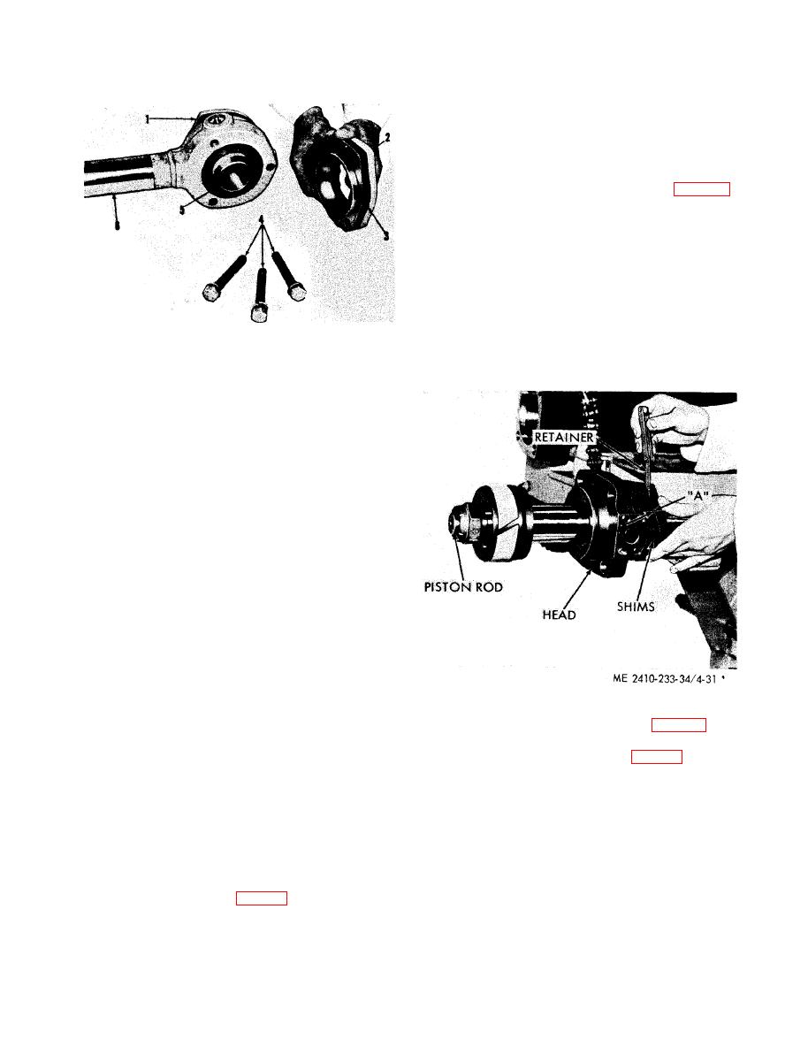
Figure 4-30. Piston rod bearing disassembly. |
|
||
| ||||||||||
|
|
 (4) Separate and oil all of the rings in packing
(11). Install one ring of packing at a time into head
(6) so the open part of the V is facing toward head.
Be sure rubber pressure ring (12) is located as
shown.
(5) Using retainer (5), tap the packing firmly
into place in the head.
(6) While holding retainer firmly seated
against packing, measure clearance (A, fig. 4-31)
between retainer and head with a thickness gage.
(7) Remove the head with the packing from
the piston rod, leaving the retainer on the rod.
(8) Install shims on the rod with a total
thickness of 0.010 inch to 0.015 inch less than the
measured clearance (A). This will preload the
packing properly when the retainer is tightened into
place.
CAUTION
1
Bearing
When installing the head on the rod, be
2
Bearing
careful not to damage the packing.
3
Shims
4
Bolts
5
Trunnion
6
Piston rod
d. Cleaning. Clean all parts with cleaning solvent
(Fed. Spec. P-D-680) and dry with lint-free cloth.
e. Inspection and Repair.
(1) Inspect the cylinders for scoring, pitting,
and wear. Inside diameter (new) is 4.7495
0.0015 inches. Maximum permissible inside
diameter is 4.7645 inches. Repair or replace a
damaged or worn cylinder.
CAUTION
Do not weld on the cylinder assemblies
as scoring may result from the bore
shrinkage.
(2) Replace all seals, packing, and wear rings.
(3) Inspect the rod end bearing for scoring,
damage, and wear. Replace as required.
(4) Inspect the piston rod for nicks, burrs,
pitting, distortion, and wear. Repair or replace a
damaged or distorted rod. Remove minor nicks and
(9) Install new backup ring (7, fig. 4-27) and
burrs using a fine emery stone. Pitted, scored, or
preformed packing (8) on the head.
worn rods may be repaired by metalizing or
chrome-plating and regrinding to original size. A
(10) Install inserts (3 and 4, fig. 4-32) with the
milled end pointing away from the piston surface,
non-corrosive metal will be used to metalize shafts.
and positioned as shown.
(5) Inspect trunnion arm bearings for damage
and wear. Replace all defective parts.
NOTE
f. Reassembly.
The bores in piston (1) which contain inserts and
plungers must be free of dirt or foreign matter.
(1) Assembly trunnion (5) and bearings (2)
and (1) in piston rod (6). Use shims (3) as required
(11) Chill the inserts before installing. Install
(between bearings and piston rod eye) to obtain a
one insert into the piston until it is flush with the
free running fit between trunnion and bearings.
piston surface. Turn the piston over and place
(2) Install seal (13, fig. 4-27) in retainer (5)
plunger (2) into the piston. Position and press the
with the lip of the seal facing away from the
other insert into the piston until it is flush with the
retainer.
piston surface. Check the plunger for moving
(3) Place retainer (5), packing (11) and head
freely. Install remaining inserts and plunger in a
(6) on the piston rod.
similar manner.
|
|
Privacy Statement - Press Release - Copyright Information. - Contact Us |
