 |
|||
|
|
|||
|
Page Title:
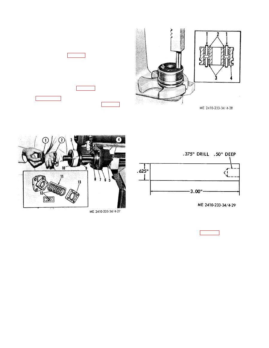
Figure 4-27. Disassembling piston and head. |
|
||
| ||||||||||
|
|
 CAUTION
Extend piston rod (4) out of the
cylinder before removing bolts (3). This
will prevent possible scoring of
cylinder walls when removing the
piston from the cylinder.
(5) Remove the head, piston rod, and piston.
(6) Remove nut (1, fig. 4-27) and washer (2).
(7) Remove piston (10).
(8) Remove wear ring (3) by expanding it
slightly and sliding it off piston (10).
(9) Expand the outer ring of seal assembly (9)
and remove the outer and inner rings.
(10) Press plungers (1, fig. 4-28) inserts (2)
and (3) from piston (4), using a driver fabricated as
shown in figure 4-29).
(11) Remove preformed packing (8, fig. 4-27)
and backup ring (7).
(12) Remove head (6).
1
Plunger
(13) Remove bolts (4) securing retainer (5) to
2
Insert
the head.
3
Insert
4
Piston
Remove packing rings (11), rubber
(14)
1
Nut
pressure ring ( 12), and seal (13).
2
Washer
Wear ring
3
(15) Remove bolts (4, fig. 4-30) securing
4
Bolts
bearings (1) and (2) and shims (3) to piston rod
5
Retainer
(6).
Cylinder head
6
(16) Remove trunnion (5) from piston rod (6).
Backup ring
7
Preformed packing
8
Seal assembly
9
Piston
10
Packing rings
11
12
Rubber pressure ring
13
Seal
|
|
Privacy Statement - Press Release - Copyright Information. - Contact Us |
