 |
|||
|
|
|||
|
|
|||
| ||||||||||
|
|
 h. Inspection and Repair.
c. Intermediate Shaft Assembly. Install in-
t e r m e d i a t e shaft with 0.004 inch to 0.007 inch end
( 1 ) Inspect bearings for corrosion, roughness,
play bearings.
a n d wear. Replace corroded, rough, or excessively
worn bearings (para 2-6).
d. Bevel Gear Shaft Assembly.
(2) Inspect all gears for chipped, pitted,
(1) Place all parts into winch case in the same
o r d e r they were removed.
c r a c k e d , or excessively worn teeth. Replace gears
w h i c h are chipped, cracked or excessively worn or
(2) Line up the marked pipe plugs in outer
d i a m e t e r of the retainer plate in
the clutch packs,
pittted. TB-ENG-364 may be used as a guide for
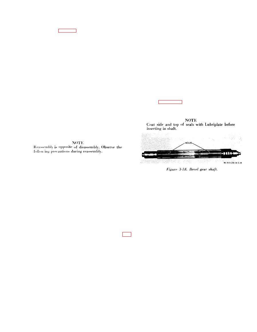
with holes in the bevel gear shaft
splines. (Only one
determining gear replacement.
of the plugs will be correct as
cross hole goes
(3) Inspect housing and covers for cracks,
b r e a k s and other damage. Repair by welding (TM
through one major diameter
and
one
miner
9-237), or replace the part.
diameter of spline).
(4) Inspect clutch disks for scoring, cracks,
( 3 ) Sling the bevel gear shaft.
d a m a g e d teeth, war page, or a burned blue-black
( 4 ) Lower the shaft through side frame, being
appearance.
Replace burned, warped, or ex-
c e r t a i n that the match marks on the shaft line up
cessively worn disks. Replace disks which have:
with the match marks on the clutches. The two
holes in the shaft (for hydraulic oil to the clutches)
( a ) Chipping on the edge of the disk.
shown in figure 3-18 will then line up with the holes
(b) Cracks at the root of any of the teeth.
in the clutch retainer plate. Do not use a hammer to
(c) W o r n t e e t h o n l y w h e n w e a r h a s o b -
viously
changed
tooth
contour.
d r i v e the shaft through the component parts.
(d) Excessive foreign material imbedded in
the face.
3-15. Winch Reassembly
a.
Clutch
Reassembly.
(1) Dish in separator plate must all face same
w a y as a unit. The direction of the unit is unim-
portant.
( 2 ) The forward and reverse clutch packs are
(5) Fix the shaft in place and revolve winch to
i n t e r c h a n g e a b l e but the spiders are not.
upright position.
(3) Never assemble a clutch pack dry. Presoak
( 6 ) Lock the bearings on the end of the shaft
all parts in oil.
that is towards brake compartment with snap rings
( 4 ) Small parts and passages must be free of
provided.
d i r t and foreign matter.
(7) Install the bearing nut on the opposite end
(5) When sliding the clutch piston into the
(torque to 200 ft-lb 25) and lock it with lock-
retainer plate, be certain that the O -rings (9) and
w a s h e r provided. (Always use new lockwasher). Do
(10) are well lubricated
and
are
seated
in
their
not install metal seal rings on ends of shaft.
r e s p e c t i v e grooves.
( 8 ) Adjust end play to 0.000-0.004 by use of
( 6 ) When assembled, the holes in the clutch
s h i m s under each bearing retainer.
hub will be in line with the oil cooling valve.
(9) Remove bearing retainers and install metal
(7) Blanked out teeth on friction discs ((6), fig.
seal rings on ends of shafts. Be sure these seal rings
3-17) must be in line.
a re n o t b r o k e n o r d a m a g e d
when
reinstalling
(8) Assembled clearance to be from 0.040 inch
b e a r i n g retainers.
to 0.070 inch. U S e s h i m s a s r e q u i r e d .
e. Brake Shaft Assembly.
( 9 ) T o r q u e c a p s c r e w s (1) with 70 ft-lb), set-
(1) Install brake shaft with 0.006 inch to
screws
(12)
with
40
ft-lb.
0.009 inch end play in bearings.
b. Drum Shaft Assembly.
(2)
Apply
Plastic
Lead
Seal
No.
2
or
( 1 ) Check all oil seals and install drum and
e q u i v a l e n t to threads of capscrews holding oil seal
drum shaft.
r e t a i n e r at brake end of shaft.
(2) Add two quarts of HDO 30
oil
to
drum
f. Power Takeoff Assembly.
c a v i t y before installing rh bearings.
(1) Install the power takeoff shaft. Be sure the
(3) Bolt drum gear to drum torquing the bolts
bevel pinion is in place and snapring properly
to
140 ft-lb lubed or 225 ft-lb) dry.
installed.
|
|
Privacy Statement - Press Release - Copyright Information. - Contact Us |