 |
|||
|
|
|||
|
Page Title:
Figure 3-10. Bearing and clutch drive gear removal. |
|
||
| ||||||||||
|
|
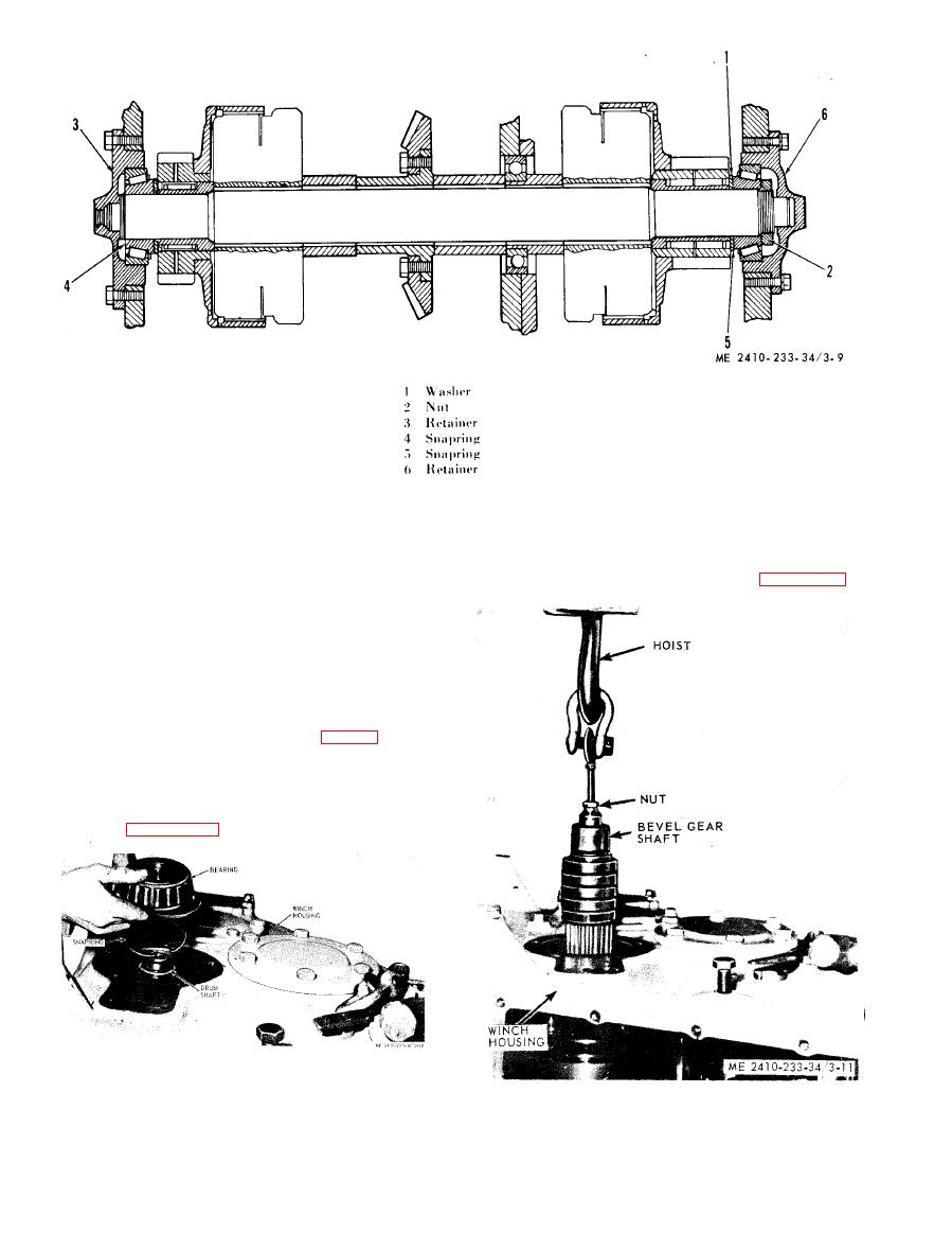 (11) Insert a 5/8 inch (UNF) bolt (with a ring
(2) Remove bearing retainer taking care to
or washer welded to it) into the threaded end of the
protect shims.
b e v e l gear shaft.
(3) Remove the rh bearing retainer (6).
(12) Pull shaft Slowly as shown in figure 3-11.
( 4 ) Loosen bearing nut (2) enough to permit
removal of snap ring (4).
( 5 ) Replace bearing retainer (3) for support.
( I f drum is to be removed, remove lh drum shaft
nut).
( 6 ) Turn winch on its left side.
(7) Remove the top side frame cover and
d i s c o n n e c t the hydraulic line.
(8) Remove bearing nut ((2), fig. 3-9).
(9) Slide roller bearing and the spacer washer
(1) from the shaft.
(10) Remove the
internal
snap
ring
(4)
retaining the bearing and clutch drive gear as
shown in figure 3-10.
|
|
Privacy Statement - Press Release - Copyright Information. - Contact Us |
