 |
|||
|
|
|||
|
Page Title:
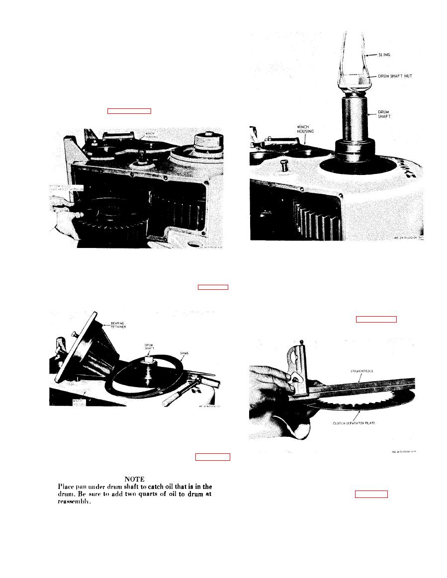
Figure 3-12. Intermediate gear and drum pinion removal. |
|
||
| ||||||||||
|
|
 (13) Do not pound or drive on the ends of the
b e v e l gear shaft.
( 1 4 ) Slide the shaft completely away from the
u n i t freeing all component parts on the shaft.
e. Intermediate Shaft Removal.
(1) Remove bearing retainer.
( 2 ) Insert puller screw in shaft.
(3) Pull shaft,
(4) Remove intermediate
gear
and
drum
pinion shown in figure 3-12.
g. Clutch Disassembly.
f. Drum Shaft Removal.
(1) Overheating due to slipping or lack of
(1) Unscrew drum shaft nut.
cooling oil will cause most damage to the discs and
(2) Remove bearing retainer shown in figure 3-
s e p a r a t o r plates. Overheating causes both parts to
13.
warp which causes clutch drag. The clutch discs are
flat. The separators are hardened steel with a slight
dish built into them as shown in figure 3-15.
Remove place bolts in drum gear.
(3)
(4)
Rethread nut on shaft.
Sling shaft using nut.
(5)
(6)
Pull shaft straight up as shown in figure 3-
14.
NOTE
THE HYDRAULIC CLUTCH MUST BE SERV-
I C E D IN A CLEAN AREA. The clutch pack
contains two parts: The clutch ((1), fig. 3-16) contains
friction discs and separator plates, and the clutch
spider (2). The two parts are not fastened together and
may be separated by sliding them apart as shown. The
clutch is held together by six flathead capscrews that
are locked on the back side by six setscrews.
|
|
Privacy Statement - Press Release - Copyright Information. - Contact Us |