 |
|||
|
|
|||
|
|
|||
| ||||||||||
|
|
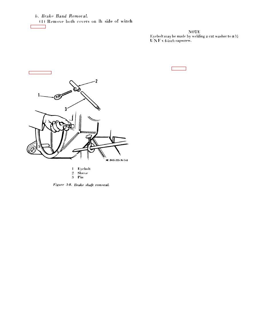
 (2) Thread eyebolt (1) into spring anchor
sleeve (2) and, using a pry bar as shown (to relieve
tension on spring), remove anchor pin (3)
(fig. 3 - 7 ) .
(2) Release brake (subpara c (2) below).
(3)
With
brake
band
in
released
position,
remove snap ring.
( 1 ) Remove pins and slide the drum from the
(3) Remove bearing retainers from both ends
s h a f t with the brake band and crank attached.
o f shaft through opening in rh side frame.
c. Brake Shaft Remoual.
d. Bevel Gear Shaft Removal.
(1) To remove brake springs, remove pipe plug
(1) Disconnect the hydraulic line to bearing
from housing and insert an eyebolt as shown in
retainer ((3), fig. 3-9).
|
|
Privacy Statement - Press Release - Copyright Information. - Contact Us |