 |
|||
|
|
|||
|
|
|||
| ||||||||||
|
|
 TM 5-2410-233-23
HYDRAULIC TILT CONTROL VALVE REPLACEMENT - CONTINUED
0150 00
INSTALLATION - CONTINUED
WARNING
Use extreme caution when handling heavy parts. Provide adequate support and use assistance during pro-
cedure. Failure to follow this warning may result in injury.
NOTE
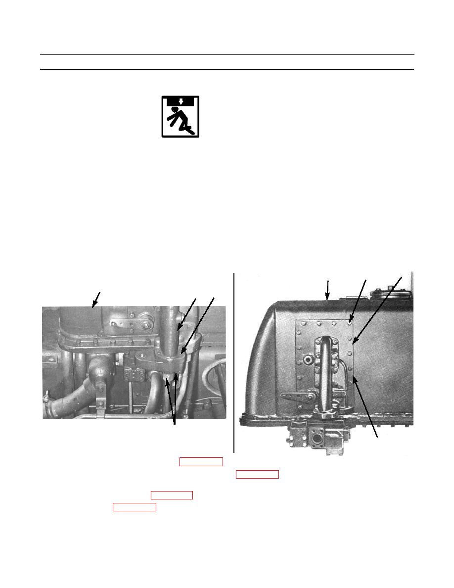
Tilt control valve, manifold and mounting plate as an assembly weighs 70 lb (35 kg).
Apply a small amount of gasket forming compound on hydraulic tank to keep gasket in place.
10.
Position new gasket (10) on mounting plate (8). With assistance, install mounting plate (8), manifold (3) and tilt control
valve (20) as an assembly on hydraulic tank (9).
11.
Install 18 new lockwashers (7) and capscrews (6) securing assembly to hydraulic tank (9).
12.
Install two new lockwashers (5) and capscrews (4) to manifold (3).
13.
Connect hydraulic lines (1 and 2) to manifold (3).
8
6,7
9
9
4,5
3
386-743
1,2 (HIDDEN)
10 (HIDDEN)
386-745
14.
Connect blade control lever and linkages (WP 0152 00).
15.
Refill hydraulic tank and bleed air from system, as required (WP 0165 00).
16.
Operate tractor and ensure hydraulic tilt control valve is operating properly and no leaks are evident. Check tilt circuit
pressures and adjust as needed (WP 0167 00).
17.
Install floor plates (WP 0135 00).
END OF WORK PACKAGE
0150 00-7
|
|
Privacy Statement - Press Release - Copyright Information. - Contact Us |
