 |
|||
|
|
|||
|
|
|||
| ||||||||||
|
|
 TM 5-2410-233-23
WINCH CONTROL LEVERS AND LINKAGE REPLACEMENT - CONTINUED
0142 00
INSTALLATION - CONTINUED
NOTE
Both control cable ends are threaded in clevis approximately 1/4 in. (6 mm). Adjustment of cables is per-
formed later in installation step 10.
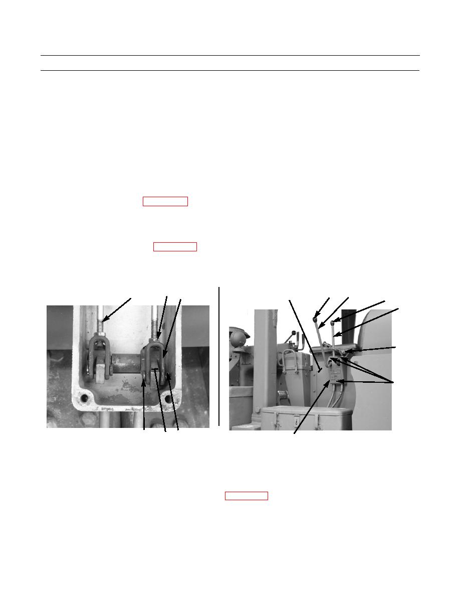
7.
Thread nut (8) onto control cable (9). Install control cable through clevis (12).
8.
Install clevis (12) to winch control lever (2) and secure with pin (11) and new cotter pin (10). Thread nut (8) to clevis.
Do NOT fully tighten nut.
9.
Repeat steps 7 and 8 for other control cable (9).
10.
Adjust winch control cables (WP 0141 00).
11.
Position control bracket (5) and control lock (7) as an assembly on seat base (6).
12.
Install three new lockwashers (4) and capscrews (3) to secure control bracket (5) to seat base (6).
13.
Install left armrest on seat base (WP 0137 00).
14.
Install two knobs (1) to winch control levers (2).
8
2
9
1
12
6
1
2
7
3,4
(HIDDEN)
386-088
10
11
386-087
2
5
NOTE
If tractor is equipped with a winterized cab, install sound suppression panels.
15.
Install top access cover to winch control valve housing (WP 0140 00).
16.
Operate winch and check for proper operation (TM 5-2410-233-10).
END OF WORK PACKAGE
0142 00-4
|
|
Privacy Statement - Press Release - Copyright Information. - Contact Us |
