 |
|||
|
|
|||
|
Page Title:
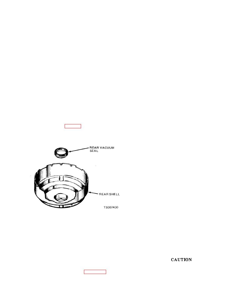
Figure 9-9. Installing Vacuum Seal. |
|
||
| ||||||||||
|
|
 TM 10-3930-633-34
plunger and, using hands only, screw rear plate
NOTE
DO NOT remove seal unless a new seal is available.
onto front plate hub. To tighten plates, place 1-
1 / 1 6 " hex bar stock in vise and set plate
b. Cleaning.
(1) After disassembly, all metal parts should
assembly, front plate down, on hex bar. Using air
be cleaned in solvent, Federal Specification P-D-
channel slot or rear plate edges, hand torque
680. Plastic parts and rubber parts should be
plates to 120 - 180 in./lbs. Remove plate
cleaned ONLY by wiping with a cloth moistened
assembly from vise. Install rear diaphragm on
in the same type solvent. Care should be taken to
rear plate and over lip of center plate. Assemble
prevent chipping or cracking of plastic parts.
diaphragm spring retainer over rear diaphragm
Replace all rubber parts,
except power
and lip of center plate. Using fingers only, press
retainer onto center plate until it seats against
diaphragms. After parts have been cleaned, use
clean (filtered) dry compressed air to blow dirt
shoulder of center plate.
and solvent out of recesses and internal passages.
(3) Apply talcum powder to inside wall of
c. Inspection. Inspect all parts for damage or
rear shell. Apply hydraulic brake fluid (or
excessive wear. The power diaphragms must be
equivalent) liberally to bearing seal in rear shell.
free of kinks, cracks and tears. Replace any
Apply hydraulic brake fluid (or equivalent)
damaged, worn or chipped parts.
liberally to cutouts around edge of front shell.
d. Assembly.
Clamp fixture base in vise and insert rear shell
studs through matching holes in base. When
(1) If vacuum seal and bearing was removed
from rear shell, press new seal into shell cavity,
assembling the plate and diaphragm assembly in
the rear shell, the lugs on the center plate must be
plastic side first (fig. 9-9), until flat rubber
aligned between the lances on the rear shell.
surface is about 5/16" below flat inside shell
Carefully guide valve housing sleeve through
surface (.305" minimum).
bearing seal in rear shell keeping center plate and
diaphragms in correct alignment. Work outer rim
of front diaphragm into rear shell so that outer
rim is under each of the retaining lances on the
rear shell. Place large diameter end of diaphragm
return spring over front plate hub and position
front shell on spring so that scribe marks on front
and rear shells will be aligned when shells are
twist-locked in place. Place bar wrench over studs
of front shell and then attach clamp bar with hook
bolts to base. Before tightening center bolt, make
certain cut-outs on front shell are aligned with
locks on rear shell. Guide rim of diaphragm into
front shell. Tighten center bolt until edge of front
shell will clear lances on rear shell. Twist front
shell clock wise in relation to the rear shell until
stop is contacted. Remove tools from power
cylinder.
(2) Install front diaphragm on front plate.
(4) Apply hydraulic brake fluid liberally to
Apply a light coat of hydraulic brake fluid to
entire surface of reaction disc and to piston end of
outside surface of front plate hub and liberally to
hydraulic pushrod. Place reaction disc on piston
the seal in the center plate hub. Carefully guide
end of pushrod. Apply Bendix Type "O"
center plate and seal assembly, seal side first,
Lubricant (or equivalent) sparingly on shaft of
onto front plate hub. Apply hydraulic brake fluid
pushrod, keeping lubricant away from adjusting
lightly to the front and rear bearing surfaces of
screw end of pushrod.
the valve plunger, being careful not to get any
lubricant on the rubber grommet inside the
Lubricant must not be allowed to get on
plunger. Assemble valve plunger return spring on
adjusting screw or threads.
valve plunger as shown in figure 9-6, and set
(5) Insert pushrod with reaction disc stuck
spring and plunger in recess of front plate hub,
to it into reaction disc hub of front plate. Twist
grommet side up. Place vacuum seal firmly
and press on pushrod to make certain disc is
against shoulder on outside of front plate hub. Set
seated firmly. Assemble seal, support plate side
rear plate, threaded bore down, over valve
|
|
Privacy Statement - Press Release - Copyright Information. - Contact Us |
