 |
|||
|
|
|||
|
Page Title:
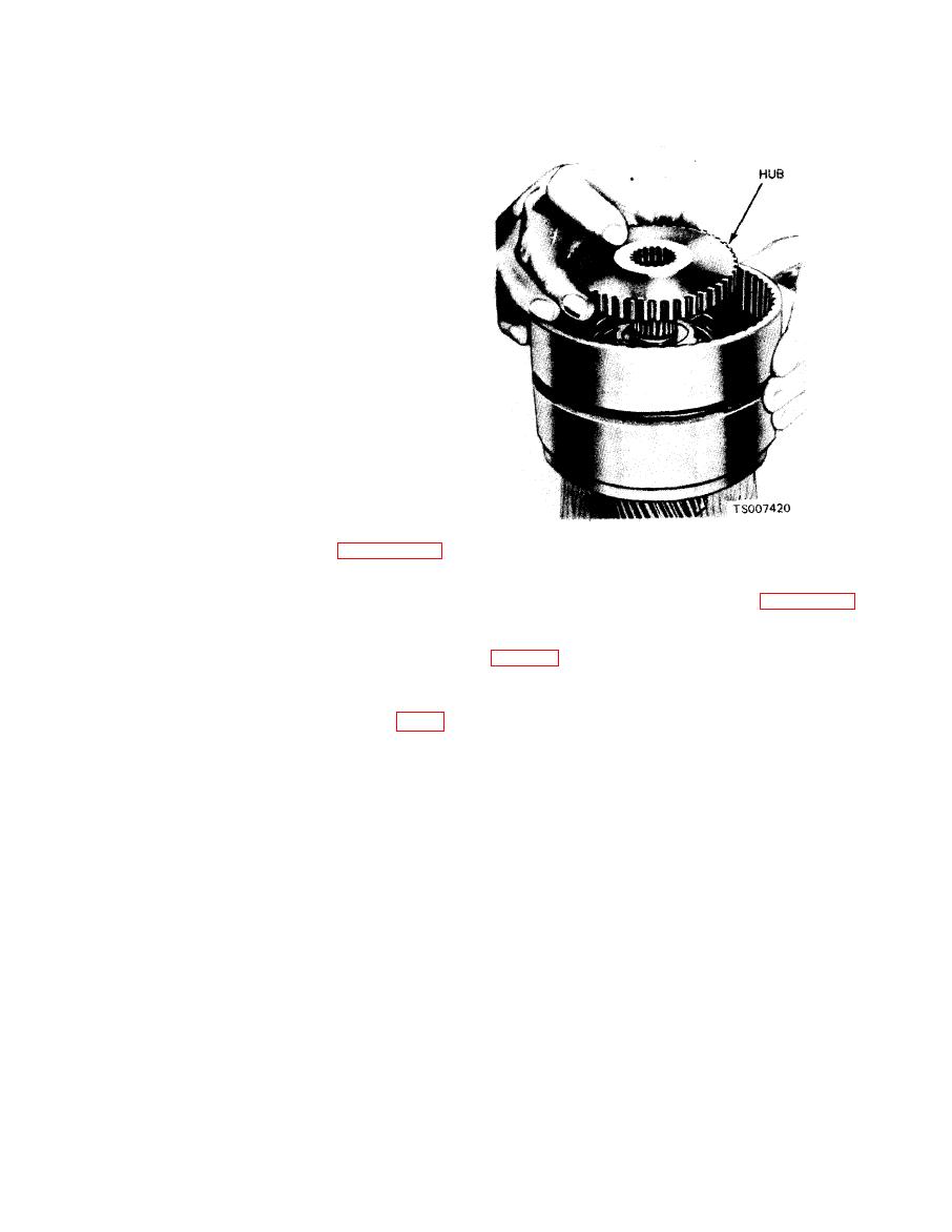
Figure 7-32. Installing Front Clutch Hub. |
|
||
| ||||||||||
|
|
 TM 10-3930-633-34
that does not slide freely on the serrations or that
is not flat.
(6) Check the clutch hub thrust surfaces for
scores and the clutch hub splines for wear.
(7) Inspect the turbine shaft bearing surfaces
for scores. If excessive clearance or scores are
found, discard the unit.
(8) Check the splines on the turbine shaft for
wear and replace the shaft if the splines are ex-
cessively worn. Inspect the bushing in the turbine
shaft for scores.
c. Assembly.
(1) Lubricate all parts with transmission
fluid. Install a new piston inner seal ring in the
clutch cylinder. Install a new piston outer seal in
the groove in the piston.
(2) Install the piston in the clutch housing.
Make sure the steel bearing ring is in place on the
piston.
(3) Position the release spring in the clutch
cylinder with the concave side up. Place t h e
release spring compressor on the spring, and
compress the spring with an arbor press. Then
install the snap ring as shown in figure 7-29.
Make sure the snap ring is fully seated in the
(6) Install the pressure plate in the clutch
groove.
cylinder with the bearing surface up (figure 7-33).
(4) Install the front clutch housing on the
Install the composition and the steel clutch plates
primary sun gear shaft by rotating the clutch
alternately, starting with a composition plate
units to mesh the rear clutch plates with the
serrations on the clutch hub. Do not break the
are used, soak the plates in automatic trans -
seal rings.
mission fluid for 15 minutes before they are
(5) Install the clutch hub in the clutch
assembled.
cylinder with the deep counterbore down (fig. 7-
32). Install the thrust washer on the clutch hub.
|
|
Privacy Statement - Press Release - Copyright Information. - Contact Us |