 |
|||
|
|
|||
|
Page Title:
Figure 6-17. Checking Valve Stem Clearance. |
|
||
| ||||||||||
|
|
 TM 10-3930-633-34
the pits and grooves. If the edge of the valve head
16), replace the valve as the valve will run too hot
in the engine.
(2) The interference fit of the valve and seat
should not be lapped out.
(3) Remove all grooves or score marks from
the end of the valve stem, and chamfer it as
necessary. Do not remove more than 0.010 inch
from the end of the valve stem.
(4) If the valve and/or valve seat has been
refaced, it will be necessary to check the clearance
between the rocker arm pad and the valve stem
with the valve train assembly installed in the
engine.
b. Select Fitting Valves. If the valve stem to
valve guide clearance exceeds the wear limit,
ream the valve guide for the next oversize valve
stem. Valves with oversize stem diameters of
0.003, 0.015 and 0.030 inch are available for
service. Always reface the valve seat after the
valve guide has been reamed.
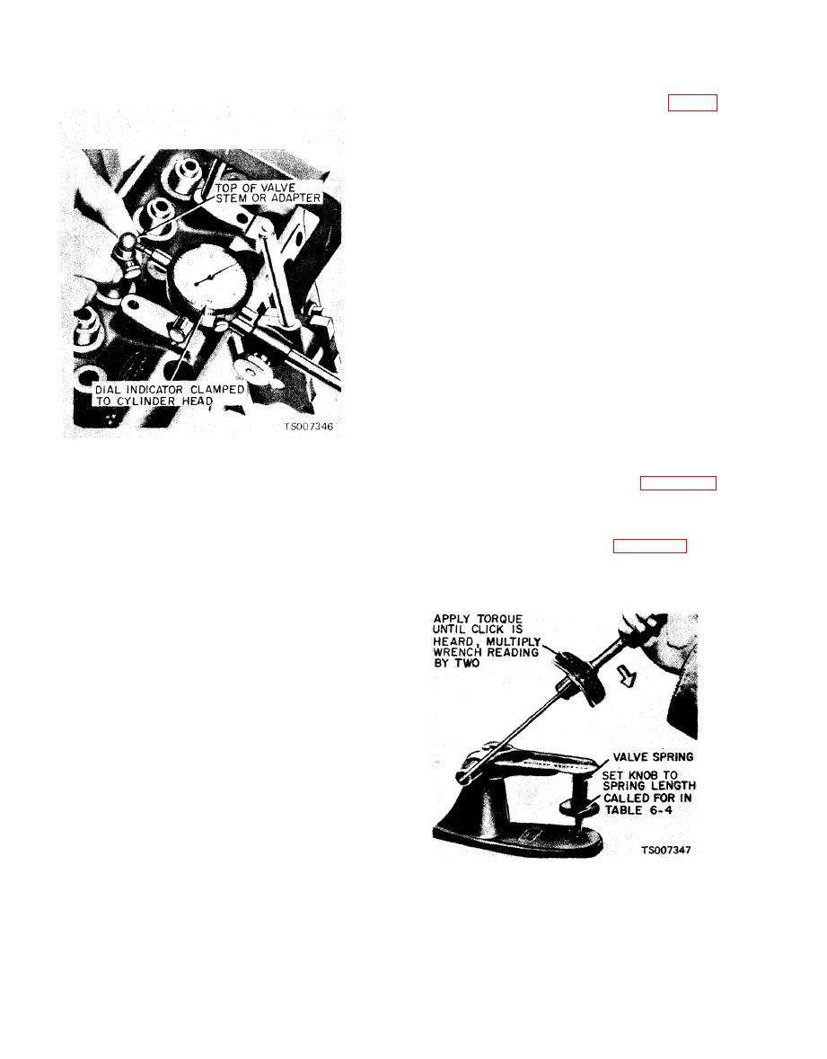
a. Checking Spring Pressure. Check the valve
(6) Install the tool on the valve stem until it
spring for proper pressure as shown in figure 6-18
is fully seated, and tighten the knurled setscrew
at the specified spring lengths. Weak valve
firmly. Permit the valve to drop away from its
springs cause poor performance; therefore, if the
seat until the tool contacts the upper surface of
pressure of any spring is lower than the wear
the valve guide.
limit, replace the spring, See table 6-4 for
(7) Position the dial indicator with its flat tip
dimensions and readings.
against the center portion of the tool's spherical
section at approximately 90 degrees to the valve
stem axis. Move the tool back and forth in line
with the indicator stem. Take a reading on the
dail indicator without removing the tool from the
valve guide upper surface. Divide the reading by
two, the division factor for the tool.
a. Machining. The valve refacing operation
should be closely coordinated with the valve seat
refacing operations to that the finished angles of
the valve face and of the valve seat will be to
specifications and provide a compression tight fit.
Be sure that the refacer grinding wheels are
properly dressed.
(1) If the valve face runout is excessive
and/or to remove pits and grooves, reface the
valves to a true 44 degree angle. Remove only
enough stock to correct the runout or to clean up
|
|
Privacy Statement - Press Release - Copyright Information. - Contact Us |
