 |
|||
|
|
|||
|
Page Title:
Figure 6-15. Value Seat Refacing. |
|
||
| ||||||||||
|
|
 TM 10-3930-633-34
(2) If the valve seat width exceeds the
maximum limit, remove enough stock from the
top edge and/or bottom edge of the seat to reduce
the width to specifications.
(3) Use a 60 degree angle grinding wheel to
remove stock from the bottom of the seats (raise
the seats) and use a 30 degree angle wheel to
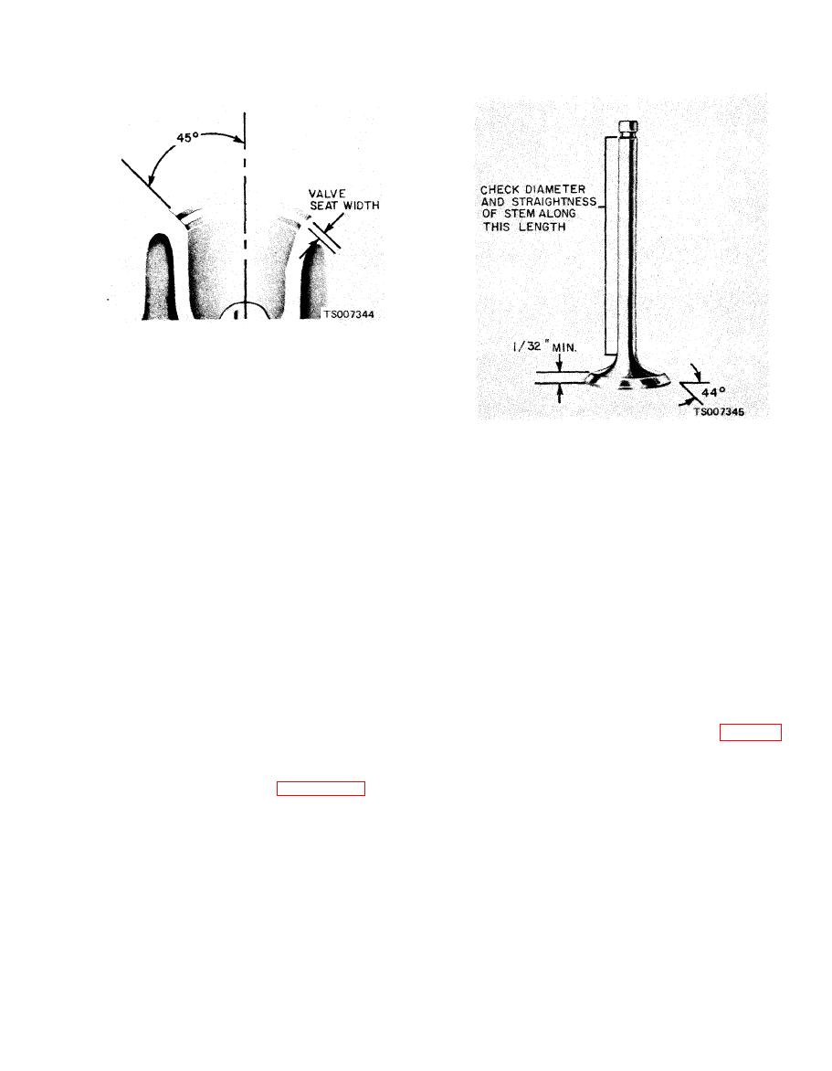
(1) Inspect the valve face and the edge of the
remove stock from the top of the seats (lower the
head for pits, grooves, or scoring.
seats).
(2) Check the stem for straightness and for
(4) The finished valve seat should contact
cracks or grooves and scoring around the lock
the approximate center of the valve face. It is
area.
good practice to determine where the valve seat
(3) Check the head of the valve for burning
contacts the face. To do this, coat the seat with
or erosion, cupping, warpage or cracks. While
Prussian blue and set the valve in place. Rotate
minor pits or grooves may be removed during
the valve with light pressure. If the blue is
r e f a c i n g , badly damaged valves should be
transferred to the center of the valve face, the
replaced.
contact is satisfactory. If the blue is transferred
(4) Check the valve face runout. It should
to the top edge of the valve face, lower the valve
not exceed the specified wear limit. If the runout
exceeds 0.002 inches, the valve should be replaced
seat. If the blue is transferred to the bottom edge
of the valve face, raise the valve seat.
or refaced.
(5) Check the valve stem to valve guide
6-17. Valve Cleaning and Inspection
clearance of each valve in its respective valve
a. Cleaning. Remove carbon deposits and
guide with a dial indicator as shown in figure 6-
sludge or varnish formation from valve stems,
17. Use a flat end indicator point. Clearance
seat, and faces with a fine wire brush or buffing
should not exceed 0.0010 to 0.0027 for new
wheel.
valves. Maximum wear limit for valves in service
b. Inspection. Refer to figure 6-16 for all
is 0.0055.
inspection and measurement points, and proceed
as follows:
|
|
Privacy Statement - Press Release - Copyright Information. - Contact Us |
