 |
|||
|
|
|||
|
Page Title:
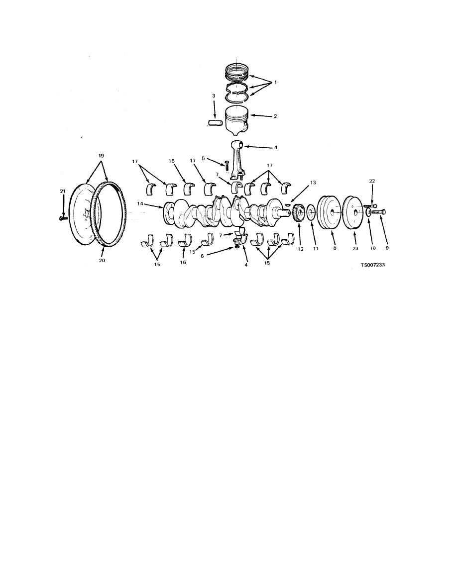
Figure 6-7. Crankshaft and Pistons. |
|
||
| ||||||||||
|
|
 TM 10-3930-633-34
13.
Key
1.
Piston ring set
14.
Crankshaft
2.
Piston and pin assembly
15.
Bearing half (lower)
3.
Pin
16.
Thrust bearing (lower)
4.
Rod
17.
Bearing half (upper)
5.
Screw
18.
Thrust bearing (upper)
6.
Nut
19.
Flywheel Assembly
7.
Bearing
Ring Gear
20.
8.
Pulley
Screw
21.
9.
Screw
Screw
22.
10.
Washer
Pulley
11.
Slinger
23.
12.
Gear
Figure 6-7. Crankshaft and Pistons.
cylinder head dowel pins and cylinder block drain
(21) Push each connecting rod and piston
plugs.
assembly out the top of the cylinder with the
handle end of a hammer. Avoid damage to the
(26) Disassemble the pistons, piston rings
and connecting rods, following the procedures in
crankshaft journal or the cylinder wall when
Section VI.
removing the piston and rod.
-
(27) If the camshaft gear is to be removed
(22) Remove the bearing inserts from the
from the camshaft, press the camshaft out of the
connecting rods and caps. Install the rod caps on
gear in an arbor press. Remove the thrust plate
the connecting rods from which they were
and spacer.
removed.
(28) Refer to Section IV for cylinder head
(23) Remove the main bearing caps.
and valve work.
Carefully lift the crankshaft out of the cylinder
block so that the thrust bearing surfaces are not
damaged. Remove the crankshaft rear oil seal.
Replacement
Handle the crankshaft with care to avoid possible
Specific procedures and criteria for cleaning,
fracture or damage to the finished surface.
inspection, repair, and parts replacement are
(24) Remove the main bearing inserts from
given under the individual section headings
the cylinder block and main bearing caps.
within this chapter.
(25) Remove oil dipstick tube from the
|
|
Privacy Statement - Press Release - Copyright Information. - Contact Us |