 |
|||
|
|
|||
|
Page Title:
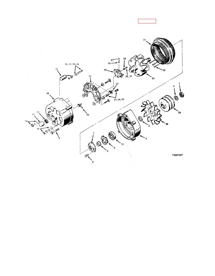
Figure 3-1. Alternator Assembly. |
|
||
| ||||||||||
|
|
 TM 10-3930-633-34
(1) Refer to figure 3-1 for parts identification
b. Removal. Refer to TM 10-3930-633-12.
and proceed as follows:
c. Disassembly.
19. Insulator
1.
Nut
2.
Washer
20. Diode
3.
Collar
21. Heat sink
22. Diode
4.
Through bolt
23. Terminal package
5.
Drive end frame
24. Terminal nut -
6.
Screw
25. Washer
7.
Bearing cap
26. Screw
8.
Collar
27. Lockwasher
9.
Gasket
28. Insulator
10.
Bearing
29. Brush
11.
Bearing
30. Spring
12.
Retainer
31. Stator
13.
Ground terminal package
32. Terminal
14.
Battery terminal package
33. Rotor
15.
Capacitor
34. Frame
16.
Screw
35. Pulley
17.
Washer
18. Washer
36. Fan
with a screwdriver at the stator slot. A scribe
(2) Remove the four through bolts (4).
mark should be made on the parts to aid in
Separate the drive end frame (5) and rotor
positioning at reassembly.
assembly (33) from the stator (31) by prying apart
|
|
Privacy Statement - Press Release - Copyright Information. - Contact Us |
