 |
|||
|
|
|||
|
Page Title:
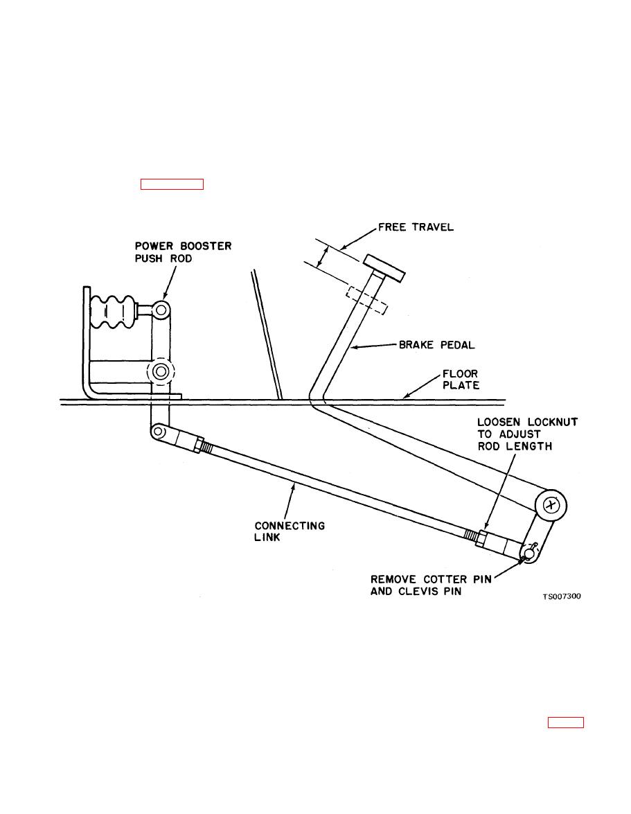
Figure 4-46. Adjusting Pedal Free Travel |
|
||
| ||||||||||
|
|
 TM 10-3930-633-12
lining wear and excessive fuel consumption.
(3) Loosen locknut.
Using a ruler, measure brake pedal free travel.
(4) Rotate clevis to obtain specified pedal free
(Depress pedal by hand.) Clearance should be
travel.
measured from top pedal position to where the
(5) Tighten locknut to hold adjustment.
pedal meets resistance from the master cylinder.
(6) Reinstall clevis pin and cotter pin.
When pedal meets resistance from the master
(7) If the brake pedal travels beyond the free
cylinder, the distance traveled should be to
travel distance, this could indicate either of the
of an inch. If the free travel is incorrect, adjust as
following conditions:
follows:
(a) Lack of fluid in the reservoir.
(1) Locate the pedal to push rod connecting
(b) Air in the brake system lines.
link, shown in figure 4-46.
(c) Brake linings need adjustment or
(2) Remove cotter pin and clevis pin from one
replacement.
end of this connecting link.
tighten all hydraulic connections and bleed
c. Power Brake System Test. As a system
screws. Apply pedal again and if pedal again falls
check, apply brakes several times with the engine
away to floor, there is a hydraulic leak in the
off and car standing still. Hold the brake pedal
system. Locate and repair leak.
applied firmly and start the engine. The brake
(3) If pedal is spongy, bleed remaining air out
pedal should drop or "fall away" slightly under
of hydraulic system.
steady pressure but then should remain firm
d. Fluid Leakage Check. The general routing
without further travel or sponginess.
of all the brake system tubing is shown in figure
(1) If pedal fails to "fall away," check
4-47. Check at each connector for loose fittings,
vacuum hose connection.
cracks, or signs of leakage, and replace damaged
(2) If pedal continues to fall, check and
|
|
Privacy Statement - Press Release - Copyright Information. - Contact Us |
