 |
|||
|
|
|||
|
Page Title:
Section XV. MAINTENANCE OF BRAKE SYSTEM |
|
||
| ||||||||||
|
|
 TM 10-3930-633-12
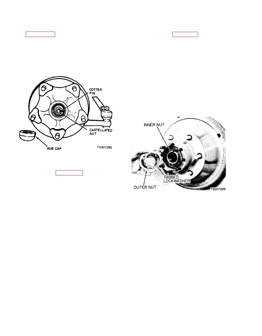
(3) If looseness or wobble is in the wheel
(3) Bend up the tangs on the lockwasher and
bearings, remove hub cap and spindle cotter pin.
remove the outer locknut and the tabbed lock-
See figure 4-44. Tighten nut with a 12-inch
washer as shown in figure 4-45.
wrench and at the same time rotate the wheel in
(4) Apply a large socket wrench to the inner
one direction and then in the other until there is a
tube nut and tighten until drag is felt when
slight bind to be sure all bearing surfaces are in
turning the hub. (Be sure brake shoes are not
contact, Then back off the nut 1/16 to 1/4 turn
causing drag). Back off the nut slightly until the
allowing the wheel to rotate freely. Secure nut at
hub turns free and install nut lock, outer tube nut
this position with a new cotter pin and replace
and tighten. Clinch nut lock to retain nuts in this
hub cap.
position.
(5) Coat the axle shaft flange to hub mating
surface with No. 2 Permatex.
(6) Insert axle shaft in tube and rotate slowly
until splines on shaft are in registry with the
differential side gears. Push shaft in and install
the retaining nuts and tighten to 52-57 ft/lbs
d. Rear Wheel Bearings Adjustment.
(1) Refer to figure 4-45. Wheel and tire,
though not shown in the illustration, should be
left on the axle.
(2) Using the jack screw holes in the axle
shaft flange, remove axle shaft after all six nuts
are removed from mounting studs.
Section XV. MAINTENANCE OF BRAKE SYSTEM
4-76. General
(1) Check the brake fluid level in the master
cylinder. The brake fluid should be within inch
The four wheel hydraulic brakes are of the in-
of the top. Fill with VV-B-680 Heavy Duty
ternal expanding shoe type. The brake system
Hydraulic Brake Fluid.
incorporates a tandem master cylinder where the
(2) Check the master cylinder filler cap vent
front axle brakes and the rear axle brakes are on
hole for obstructions. Vent must be open at all
separate hydraulic circuits. This arrangement
prevents complete loss of braking action in cases
times. Clean if necessary.
b. Brake Pedal Free Travel Check. A correctly
of failure at some point in the system. The
adjusted brake pedal is important so that the
operator's pedal effort is assisted by a vacuum
internal ports in the master cylinder are not
booster on the master cylinder push rod. Engine
blocked by the cylinder piston. An improperly
vacuum is used to operate the booster. Each
adjusted pedal will block the internal ports so
brake assembly provides a means for mechanical
adjustment of lining-to-drum clearance.
that upon releasing the brake pedal, fluid will be
trapped in the lines and hold the brake linings in
4-77. Inspection
contact with the brake drums. This will cause
a. Master Cylinder Fluid Level Check.
|
|
Privacy Statement - Press Release - Copyright Information. - Contact Us |